Basic elements and concepts of IDEF0
The history of the IDEF0 standard
IDEF0 standard
The IDEF0 methodology can be considered the next stage in the development of the well-known graphical language for describing functional systems SADT (Structured Analysis and Design Teqnique). Historically, IDEF0 as a standard was developed in 1981 by the US Department of the Air Force as part of the industrial automation program, which bore the designation ICAM (Integrated Computer Aided Manufacturing). The IDEF standards set inherited its name from this program (IDEF=ICAM DEFinition). In the process of practical implementation, the participants of the ICAM program faced the need to develop new methods for analyzing interaction processes in industrial systems. At the same time, in addition to an improved set of functions for describing business processes, one of the requirements for the new standard was the availability of an effective methodology for interaction within the "analyst-specialist". In other words, the new method was supposed to provide group work on the creation of the model, with the direct participation of all analysts and specialists involved in the project.
As a result of the search for appropriate solutions, the IDEF0 functional modeling methodology was born. Since 1981, the IDEF0 standard has undergone several minor revisions, mostly of a restrictive nature, and its last revision was released in December 1993 by the US National Institute of Standards and Technology (NIST).
The IDEF0 graphical language is remarkably simple and harmonious. The methodology is based on four main concepts:
Functional block (Activity Box);
Interface arc (Arrow);
Decomposition;
Glossary.
Let's take a closer look at these basic concepts.
Functional block (Activity Box)
The functional block is graphically depicted as a rectangle (Fig. 1) and represents some specific function within the considered system. According to the requirements of the standard, the name of each functional block must be formulated in the verbal mood (for example, “to produce services”, and not “to produce services”).
Each of the four sides of the functional block has its own specific meaning (role), while:
The top side is "Control";
The left side is "Input";
The right side is set to “Output”;
The bottom side has the meaning “Mechanism” (Mechanism).
Such a designation reflects certain system principles: inputs are converted into outputs, control limits or prescribes the conditions for performing transformations, mechanisms show what and how a function performs.
Each functional unit within the single system under consideration must have its own unique identification number.
Rice. 1. Function block.
IDEF0 requires a diagram to have at least three and no more than six boxes. These constraints keep the complexity of the diagrams and models at a level that can be read, understood, and used.
Blocks in IDEF0 are placed in order of importance, as understood by the author of the diagram. This relative order is called dominance. Dominance is understood as the influence that one block has on other blocks of the diagram. For example, the most dominant block in the diagram may be either the first of a required sequence of functions, or a planning or control function that influences all others.
The most dominant box is usually placed in the upper left corner of the diagram, while the least dominant box is placed in the right corner.
The arrangement of blocks on the page reflects the author's definition of dominance. Thus, the topology of the diagram shows which features have a greater impact on the others. To emphasize this, the analyst can renumber the blocks according to their order of dominance. The order of dominance can be indicated by a number placed in the lower right corner of each box: 1 would indicate the highest dominance, 2 the next, and so on.
Interface arc (Arrow)
Also, interface arcs are often called flows or arrows. An interface arc represents a system element that is processed by a function block or otherwise affects the function displayed by this function block.
The graphical display of the interface arc is a one-way arrow. Each interface arc must have its own unique name (Arrow Label). According to the standard, the name must be a turnover of a noun.
With the help of interface arcs, various objects are displayed that, to one degree or another, determine the processes occurring in the system. Such objects can be elements of the real world (parts, wagons, employees, etc.) or data and information flows (documents, data, instructions, etc.).
Depending on which of the sides this interface arc approaches, it is called “incoming”, “outgoing” or “controlling”. In addition, the “source” (beginning) and “receiver” (end) of each functional arc can only be functional blocks, while the “source” can only be the output side of the block, and the “receiver” can be any of the remaining three.
The name of the arrow is usually given by a noun.
The IDEF0 methodology requires only five types of interactions between blocks to describe their relationships:
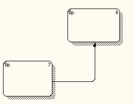
Input connection (output-input), when the output of the higher work is connected to the input of the lower one (Fig. 2);
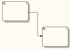
Rice. 2. Communication by input
Control connection (output-control), when the output of the higher work is connected to the control of the lower one (Fig. 3);
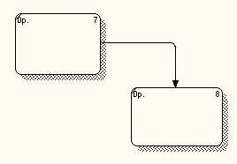
Rice. 3.Communication for management
Input feedback (output-input feedback), when the output of the lower work is connected to the input of the higher;
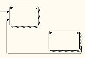
Rice. 4. Input Feedback
Control feedback (output-control feedback), when the output of the lower work is connected to the control input of the higher work;
Rice. 5. Management feedback
An output-mechanism link is when the output of one job is directed to the mechanism of another.
Rice. 6. Output-mechanism connection
Control and entry relationships are the simplest as they reflect direct actions that are intuitive and very simple.
A control relationship occurs when the output of one block directly affects a block with less dominance.
Control feedback and input feedback are more complex because they are iterative or recursive. Namely, outputs from one job affect the future execution of other jobs, which will subsequently affect the original job.
Control feedback occurs then; when the output of some block affects a block with more dominance.
Exit-mechanism relationships are rare. They reflect a situation in which the output of one function becomes a means to an end for another. Such relationships are characteristic of the distribution of resource sources (eg, required tools, trained personnel, physical space, equipment, funding, materials).
In IDEF0, an arc rarely depicts a single object. Usually it symbolizes a set of objects. Because arcs represent collections of objects, they can have multiple start points (sources) and end points (destinations). Therefore, arcs can branch and connect in various ways. The entire arc or part of it can exit from one or more blocks and end in one or more blocks.
The branching of the arcs, depicted as diverging lines, means that all or part of the contents of the arcs can appear in each branch. An arc is always labeled before a branch to give a name to the entire set. In addition, each branch of an arc may or may not be labeled according to the following rules:
Unlabeled branches contain all the objects specified in the arc label before the branch;
Branches labeled after a branch point contain all or part of the objects specified in the arc label before the branch.
Arc merges in IDEFO, shown as lines converging together, indicate that the contents of each branch go to form a label for the arc resulting from the merge of the original arcs. After a merge, the resulting arc is always marked to indicate the new set of features that emerged after the merge. In addition, each branch may or may not be flagged before a merge, according to the following rules:
Unlabeled branches contain all the entities specified in the common arc label after the merge;
Branches marked before the merge contain all or some of the objects listed in the common mark after the merge,
It should be noted that any functional block, according to the requirements of the standard, must have at least one control interface arc and one outgoing one. This is understandable - each process must occur according to some rules (displayed by the control arc) and must produce some result (outgoing arc), otherwise its consideration does not make any sense.
When constructing IDEF0 diagrams, it is important to correctly separate incoming interface arcs from control arcs, which is often not easy. For example, Figure 7 shows the “Process workpiece” functional block.
In a real process, the worker performing the processing is given a workpiece and technological instructions for processing (or safety regulations when working with the machine). It may mistakenly appear that both the workpiece and the document with technological instructions are input objects, but this is not the case. In fact, in this process, the workpiece is processed according to the rules reflected in the technological instructions, which should be respectively depicted by the control interface arc.
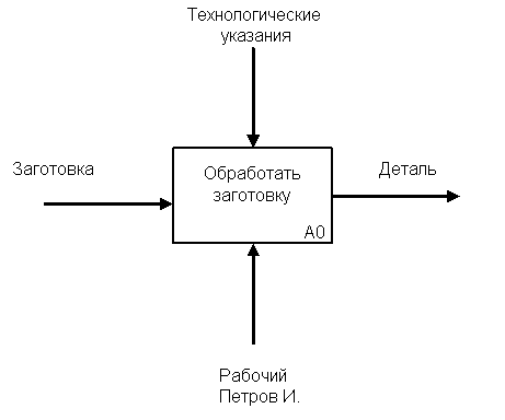
Rice. 7. Functional block "Process workpiece".
Another thing is when technological instructions are processed by the chief technologist and changes are made to them (Fig. 8). In this case, they are already displayed by the incoming interface arc, and the control object is, for example, new industrial standards, based on which these changes are made.
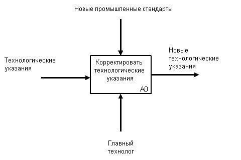
Rice. 8. Functional block "Correct technological instructions"
The above examples emphasize the seemingly similar nature of incoming and controlling interface arcs, but there are always certain distinctions for systems of the same class. For example, in the case of considering enterprises and organizations, there are five main types of objects: material flows (parts, goods, raw materials, etc.), financial flows (cash and non-cash, investments, etc.), document flows (commercial, financial and organizational documents), information flows (information, data of intent, verbal orders, etc.) and resources (employees, machines, machines, etc.). In this case, in various cases, incoming and outgoing interface arcs can display all types of objects that manage only those related to the flow of documents and information, and only resources can be displayed as arcs-mechanisms.
The mandatory presence of control interface arcs is one of the main differences between the IDEF0 standard and other methodologies of the DFD (Data Flow Diagram) and WFD (Work Flow Diagram) classes.
Decomposition
The principle of decomposition is applied when a complex process is broken down into its constituent functions. In this case, the level of detail of the process is determined directly by the developer of the model.
Decomposition allows you to gradually and structuredly represent the system model in the form of a hierarchical structure of individual diagrams, which makes it less overloaded and easily digestible.
The IDEF0 model always begins with a view of the system as a whole - a single functional unit with interface arcs extending beyond the considered area. Such a diagram with one functional block is called a context diagram, and is denoted by the identifier “A-0” (Fig. 9).
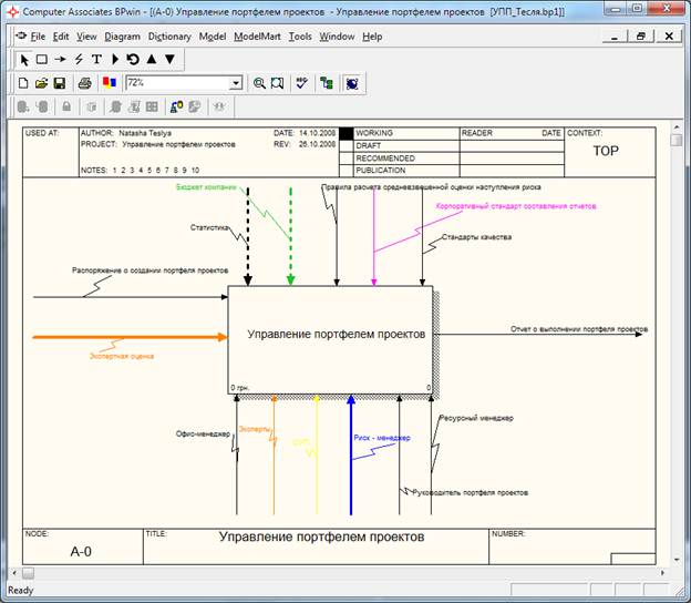
Rice. 9. Context Diagram Example
In the explanatory text for the context diagram, the purpose (Purpose) of constructing the diagram in the form of a brief description should be indicated and the point of view (Viewpoint) should be fixed.
Determining and formalizing the purpose of developing an IDEF0 model is an extremely important point. In fact, the goal determines the relevant areas in the system under study, which need to be focused first. For example, if we model the activities of an enterprise in order to build an information system based on this model in the future, then this model will differ significantly from the one that we would develop for the same enterprise, but with the aim of optimizing supply chains.
The point of view determines the main direction of the development of the model and the level of detail required. A clear fixation of the point of view allows you to unload the model, refusing to detail and study individual elements that are not necessary, based on the chosen point of view on the system. For example, functional models of the same enterprise from the point of view of the chief technologist and financial director will differ significantly in the direction of their detailing. This is due to the fact that, in the end, the financial director is not interested in the aspects of processing raw materials on production machines, and the chief technologist is not interested in the drawn schemes of financial flows. The correct choice of point of view significantly reduces the time spent on building the final model.
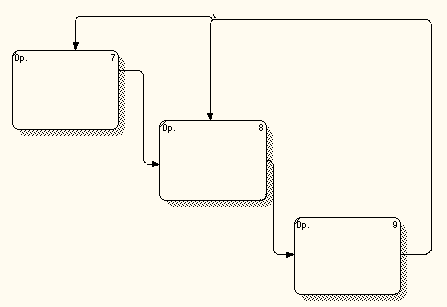
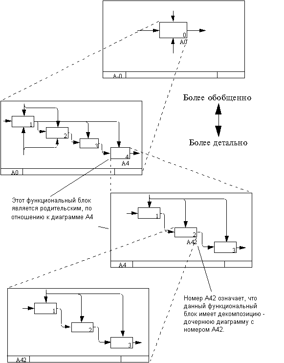
In the process of decomposition, the functional block, which in the context diagram displays the system as a whole, is detailed in another diagram. The resulting diagram of the second level contains functional blocks that display the main subfunctions of the functional block of the context diagram and is called a child diagram (Child diagram) in relation to it (each of the functional blocks belonging to the child diagram is respectively called a child block - Child Box). In turn, the functional block - the ancestor is called the parent block in relation to the child diagram (Parent Box), and the diagram to which it belongs is called the parent diagram (Parent Diagram). Each of the subfunctions of the child diagram can be further detailed by a similar decomposition of its corresponding functional block. It is important to note that in each case of decomposition of a functional block, all interface arcs included in this block or outgoing from it are fixed on the child diagram. This achieves the structural integrity of the IDEF0 model. The principle of decomposition is clearly shown in Figure 10. You should pay attention to the relationship between the numbering of functional blocks and diagrams - each block has its own unique serial number on the diagram (the number in the lower right corner of the rectangle), and the designation at the right angle indicates the number of the child diagram for this block . The absence of this designation indicates that there is no decomposition for this block.
Often there are cases when it does not make sense to continue to consider individual interface arcs in child diagrams below a certain level in the hierarchy, or vice versa - individual arcs do not make practical sense above a certain level. For example, an interface arc depicting a “detail” at the input to the “Machining on a lathe” function block does not make sense to reflect on diagrams of higher levels - this will only overload the diagrams and make them difficult to read. On the other hand, there is a need to get rid of separate "conceptual" interface arcs and not to detail them deeper than a certain level. To solve such problems, the IDEF0 standard provides for the concept of tunneling. The designation of the “tunnel” (Arrow Tunnel) in the form of two parentheses around the beginning of the interface arc means that this arc was not inherited from the functional parent block and appeared (from the “tunnel”) only on this diagram. In turn, the same designation around the end (arrow) of the interface arc in the immediate vicinity of the receiver block means that this arc will not be displayed and will not be considered in the child diagram of this block. Most often, it happens that individual objects and their corresponding interface arcs are not considered at some intermediate levels of the hierarchy - in this case, they first “plunge into the tunnel”, and then, if necessary, “return from the tunnel”.
 Discounted payback period
 Methodological aspects of project management
 Scrum Development Methodology