Chimneys are separate. Installation and maintenance of the Lemax turbo nozzle Connecting the turbo nozzle to the Lemax nova boiler
Igor November 2, 2016
"I bought a" LEMAX "boiler of the" PREMIUM "series with SIT 820 NOVA automatics and a" LEMAX "turbo nozzle. service center for the maintenance of gas boilers for starting the boiler and connecting the turbo nozzle to the boiler. The attachment was connected, but not quite correctly. The fan of the handpiece runs continuously. The fan does not stop when the main gas burner is off. I drew the attention of specialists to this, repeatedly tried to correct this situation. But to no avail. In the end, they left me. I have a question - how to connect the nozzle so that the fan stops when the main burner is turned off? Thanks in advance for the advice. "
In today's article, we will try to tell you what a turbo nozzle for a Lemax gas boiler is, which boilers it is suitable for, and we will try to answer the question that user Igor left on our forum on November 2.
The turbo nozzle is designed for removal of combustion products forcibly, which allows the use of gas boilers without a specially organized natural draft chimney.
For boilers with a power of 10 kW, the chimney diameter is 100 mm.
For boilers from 12.5 to 30 kW. chimney diameter 130 mm.
For boilers from 35 to 40 kW. chimney diameter 140 mm.
A fan is installed in the product for a rated voltage of 220 V. 50 Hz
The turbo nozzle consists of a housing on which a fan, item 3, with inlet and outlet nozzles is installed. A pressure switch (air pressure switch) item 4 is installed on the body and connected to the fan by a tube. All electrical connections are switched through the terminal block p. 7.
1 - The base of the turbo nozzle.
2 - Turbo nozzle cover.
3 - Fan
4 - Monostat.
5 - Monostat connection tube.
6 - Flue pipe.
7 - Terminal block.
Device and work.
The turbo nozzle control unit is designed for connection to boilers equipped with safety automation SIT 820 NOVA and SIT 845 Sigma.
The turbo nozzle forcibly removes the boiler combustion products at the signal of the thermostat (the thermostat installed on the boiler maintains the temperature at the level set by the consumer). In this case, the pressure switch (air pressure switch) closes the contacts only when the air pressure at the outlet of the turbo nozzle corresponds to the specified parameter. When the pressure in the chimney is exceeded or below the set one, the contacts will open and the boiler safety circuit will break.
In the event of an emergency stop of the turbo nozzle fan or when the flue gas outlet is shut off, the boiler stops operating, that is, the SIT 820 NOVA safety automatics (volatile boiler control unit) stops the gas supply to the main burner.
Chimney placement:
? if there is no condensate trap, it must be installed at an angle to the ground, preventing condensation from draining back. The optimum slope is 3–6 °.
? the minimum horizontal distance to doors, windows and open ventilation grilles (openings) should be 0.5 meters;
? the minimum distance to the upper edge of doors, windows and open ventilation grilles (holes) should also be 0.5 meters;
? the vertical distance from the windows located above the opening of the smoke channel - from 1 meter;
? in the area of 1.5 meters from the pipe there should be no obstacles, say, walls, pillars, etc.;
? each turn reduces the length of the pipe by: 0.5 meters - 45 degrees, 1 meter - 90 degrees;
? in order to avoid clogging and blowing out, the obligatory installation of a deflector on the chimney


TP - safety thermostat
TR - adjustable thermostat
Scheme of turbo nozzle "Lemax" for a non-volatile boiler.
TR - adjustable thermostat
VT - fan
PT - pressure switch (air pressure switch)
RP - intermediate relay
Diagram of connecting the Lemax turbo nozzle to a boiler with SIT 820 Nova safety automatics and a time delay unit (PML 1100 starter and PVL-22 (21) attachment).

TP - safety thermostat
TR - adjustable thermostat
BZV - Time delay block
Scheme of turbo nozzle "Lemax"for a non-volatile boiler.

TP - safety thermostat
TR - adjustable thermostat
VT - fan
PT - pressure switch (air pressure switch)
Connection diagram of the Lemax turbo nozzle to the boiler with SIT 820 Nova safety automatic

TP - safety thermostat
TR - adjustable thermostat
Connection diagram of the Lemax turbo nozzle to a boiler with a control board.

TR - thermostat
Set of wires for connecting the Lemax turbo nozzle 
P - pink
B - white
G - blue
K - red
F / W yellow-green

1. Disconnect wire # 5 from connector # 7.
2. Connect wire # 5 to wire # 3.
3. Disconnect wire # 6 from connector # 8.
4. Wire # 6 to connect to wire # 4.
5. Wire # 1 to connect to connector # 7.
6. Wire # 2 to connect to connector # 8.
The Lemax turbo nozzle is an innovative device for the forced removal of combustion products during the operation of a heating boiler. This device allows you to buy a heating gas boiler and install it without organizing a natural draft chimney. The organization of a chimney that meets all safety rules is a laborious process that requires engineering knowledge. Moreover, the construction of a house often makes the organization of a natural chimney difficult. It is possible to significantly simplify the process of removing the boiler combustion products by installing a special nozzle.
The Lemax turbo nozzle is a small metal box that is installed directly on the boiler neck or can be connected to it with pipes. The operation of the device is provided by a radial fan and a monostat. The design of the device also provides for an element that connects the nozzle with the boiler neck and the outlet for combustion products. The use of a nozzle allows the pipe to be removed from the boiler not through the roof, but through the wall in the immediate vicinity of the boiler.
The turbo nozzle is suitable for single-circuit heating boilers, and it can also be installed on a gas double-circuit floor boiler. The device works in conjunction with single-circuit and double-circuit boilers "Lemax" of the "Premium" and "Leader" series with automatic equipment 820 NOVA SIT and volatile boilers of the "Clever" and "Wise" series. Boilers of these series can operate with or without a turbo nozzle. The turbo nozzle also works with gas heating devices "Lemax" series
1. Security measures
1.1. The turbo nozzle must be installed and put into operation by the organization
licensed to given view works. To prepare the turbo nozzle for use, only specially trained personnel with an appropriate electrical safety group, as well as knowledge of the regulatory operating documents of the facility where the product is being installed, are allowed.
1.2. Work on transportation, installation and preparation of the turbo nozzle must be carried out in the absence of voltage in its electrical circuits.
2. Preparing the product for use
2.1. The turbo nozzle is installed on the boiler, and the flue pipe is brought out into the street; during installation, it is necessary to ensure the drainage of condensate. (see Appendix A). When laying, it is necessary to ensure the required limits of fire resistance of their structures in accordance with SNiP 41-01. During the operation of the boiler, it is necessary to ensure that the air necessary for combustion is supplied to the room.
2.2. The electrical connection of the turbo nozzle must be carried out in accordance with the diagram given in Appendix B.
2.3. When operating the boiler, it is forbidden to place objects made of flammable materials closer than 200 mm (for example, fiberboard, polyurethane, polyethylene, lightweight PVC, synthetic fibers, cellulose substances, and the like).
2.4. After installation, check the correct operation of the turbo nozzle:
- after turning on the boiler, the fan starts first. Further, after the monostat contacts are closed, the main burner lights up.
- when the outlet of flue gases from the turbo nozzle is closed, the fan continues to operate, but the main burner does not light up.
2.5. If the boiler does not have an overheating sensor (95 degrees / Celsius), then it must be installed in the upper part of the heat exchanger and connected according to the "Turbo nozzle connection diagram" (see Appendix B).
OPERATING LIMITATIONS
1. The chimney from the boiler to the turbo nozzle must not create resistance to the movement of exhaust gases (no narrowing or turns are allowed).
2. The pressure at the inlet to the turbo nozzle must be at least 5 Pa.
3. The turbo nozzle is designed to operate with a rated voltage of 220 V. 50 Hz.
4. The turbo nozzle is not intended for removing combustion products from boilers operating on solid fuels, and removing smoke in case of fire, as well as for the operation of wall-mounted boilers.
5. When installing and servicing the turbo nozzle, electrical safety precautions must be observed.
MAINTENANCE
1. Maintenance must be performed at least once a year. Only specially trained personnel with an appropriate electrical safety group, as well as knowledge of the regulatory operational documents of the facility, are allowed to service. During maintenance, it is necessary to check the condition of the fan, monostat, and tubes, as well as electrical wires. Remove dust from the turbo nozzle, lubricate moving parts with machine oil if necessary.
2. After completing the work, be sure to check the performance of the turbo nozzle. (see clause 2.3.3.)
- if there is no condensate trap, it must be installed at an angle to the ground, preventing condensation from draining back. The optimum slope is 3-6 °.
- at a distance of at least 2 meters from the ground level;
- the minimum horizontal distance to doors, windows and open ventilation grilles (holes) should be 0.5 meters;
- the minimum distance to the upper edge of doors, windows and open ventilation grilles (holes) should also be 0.5 meters;
- the vertical distance from the windows located above the opening of the smoke channel - from 1 meter;
- in the area of 1.5 meters from the pipe there should be no obstacles, say, walls, pillars, etc.;
- each turn reduces the length of the pipe by: 0.5 meters - 45 degrees, 1 meter - 90 degrees;
- in order to avoid clogging and blowing out, it is mandatory to install a deflector on the chimney.
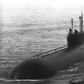 The fastest boat in the world!
 The history of the Off-White brand
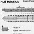 Habakkuk: how the British tried to build an aircraft carrier from ice Why the project was curtailed