CAD system. Computer-aided design systems - what it is and why CAD is used. What are CAD systems
CAD programs (computer aided design) are system complexes for design, with the help of which they automate tasks at different stages of manufacturing industrial products (design, pre-production). In the Russian-language abbreviation - CAD (computer-aided design system).
All CAD-systems, regardless of terminology, are designed to optimize the work of the engineering staff of the enterprise. If applied correctly, appropriately, they increase the productivity of individual groups of employees. And this leads to an increase in the overall performance of the staff as a whole.
CAD-systems deployed at the enterprise allow solving the following tasks:
- to reduce the labor intensity of individual operations and processes, which means to reduce the time and costs for the development and manufacture of products;
- reduce the time spent on preparing projects - with these systems, design is brought to a fundamentally different level;
- to increase the accuracy of manufacturing products without losses in speed (production efficiency even increases);
- reduce the costs that are necessary to maintain the engineering staff (which reduces the cost of the finished product);
- improve the quality of design - CAD programs bring it to a new technical and economic level;
- reduce the cost of sample modeling and testing.
CAD - complete solutions. They can be software, technical, and others. With the help of CAD, they automate the preparation of design and construction documents within the enterprise, unify design, optimize the process of making management decisions (by expanding information support), and solve other problems.
Versatility and free integration with SAP solutions
Due to their high efficiency and flexibility of products, the systems are used in various fields - from dentistry and medical prosthetics to mechanical engineering. Today CAD programs are software that is freely integrated into SAP systems, they are compatible with any of their solutions. Using special buses, you can combine CAD with PLM or CAM systems (computer aided manufacturing). The latter, designed for working with CNC machines, create numerical control algorithms, open up opportunities for the manufacture of high-quality complex-profile products in a shorter period of time.
CAD software solutions also support:
- top-level systems - CAD / CAM Unigraphics;
- complexes at the middle level - Solid Edge;
- lower-level systems - AutoCAD and others.
The programs integrate with Pro / Engineer, SolidWorks, TeamCenter, Inventor, and other products. They are easy to learn, have a "user-friendly" interface, wide functionality (you can customize them so that they meet individual customer requirements and business specifics). CAD systems support concurrent design technologies. With them, you can freely use the methods of variant optimization, mathematical modeling. Another important plus is that the price of the product is flexible. It is determined by the functionality that is selected for a specific customer, his needs, tasks, opportunities.
ASAP Consulting offers services for the development of optimized design and manufacturing solutions that use advanced automation tools. We will select CAM, CAD solutions for a specific task, help to deploy products in the enterprise, and advise on all emerging issues.
CAD system(сomputer-aided design computer support for design) is a computer-aided design system designed to carry out design work using computer technology, and also allows you to create design and technological documentation for individual products, buildings and structures.
Usually, the abbreviation CAD considered the standardized English equivalent of the term CAD... However, the concept of CAD is not a complete equivalent of CAD as an organizational and technical system: so in GOST 15971-90 this phrase is given as a standardized English equivalent of the term "computer-aided design". The term CAD in English can also be translated as CAD system, automated design system, CAE system.
A number of foreign sources establish a certain subordination of the concepts of CAD, CAE, CAM. The term CAE is defined as the most general concept, including any use of computer technology in engineering, including CAD and CAM. The term CAx (computer-aided technologies) is used to denote the entire spectrum of various automation technologies using a computer, including CAD tools.
The main purpose of creating CAD- increasing the efficiency of engineers' labor by automating work at the design and preparation stages. So, thanks to CAD, it is possible to achieve:
Reducing the complexity of design and planning;
- reduction of design time;
- reducing the cost of design and manufacture, reducing operating costs;
- improving the quality and technical and economic level of design results;
- reducing the cost of full-scale modeling and testing.
As input information CAD uses the technical knowledge of specialists who introduce design requirements, refine results, check the resulting design, modify it, etc.
The computer-aided design system is implemented in the form of a complex of applied programs that provide design, drawing, three-dimensional modeling of structures, flat or volumetric parts.
As a rule, modern CAD systems include modules for modeling a three-dimensional volumetric structure (details) and design of drawings and text design documentation(specifications, statements, etc.).
CAD classification according to GOST 23501.108-85:
Type / type of design object
- the complexity of the design object
- the level of design automation
- the complexity of design automation
- the nature of the issued documents
- the number of issued documents
- the number of levels in the structure of technical support
Classification of CAD (or CAD subsystems) by purpose:
CAD (computer-aided design / drafting) means computer-aided design, in the context of this classification, the term denotes CAD tools designed to automate two-dimensional and / or three-dimensional geometric design, create design and / or technological documentation, and general-purpose CAD.
- CADD (English computer-aided design and drafting) - design and creation of drawings.
- CAGD (English computer-aided geometric design) - geometric modeling.
- CAE (computer-aided engineering) - means of automation of engineering calculations, analysis and simulation of physical processes, carry out dynamic modeling, verification and optimization of products.
- CAA (computer-aided analysis) is a subclass of CAE tools used for computer analysis.
- CAM (English computer-aided manufacturing) - means of technological preparation of the production of products, provide automation of programming and control of equipment with CNC or GAPS (Flexible Automated production systems)). The Russian analogue of the term is ASTPP - an automated system for technological preparation of production.
- CAPP (English computer-aided process planning) - automation tools for planning technological processes used at the junction of CAD and CAM systems.
Many computer-aided design systems combine the solution of tasks related to various aspects of CAD / CAM, CAD / CAE, CAD / CAE / CAM design. Such systems are called complex or integrated.
Generally accepted international classification of CAD / CAM / CAE systems:
Drawing-oriented systems, which were the first to appear in the 70s. (and are still successfully used in some cases).
Systems that allow you to create a three-dimensional electronic model of an object, which makes it possible to solve problems of its modeling up to the moment of manufacture.
Systems supporting the EPD Electronic Product Definition concept. EPD is a technology that enables the development and maintenance of an electronic information model throughout life cycle products, including marketing, conceptual and detailed design, technological preparation, production, operation, repair and disposal.
CAD abbreviation in modern technical, educational literature and state standards stands for "Computer-aided design system", although it more closely matches the abbreviation CAD decoding "Design work automation system", but it is heavier for perception and is used much less often. Misinterpretation can often be heard - "Computer-aided design system", which is inherently erroneous, since the concept of "automatic" implies independent work systems, without human participation, and in CAD, some of the functions are performed by a person, and only individual design operations and procedures. The interpretation is also not entirely correct "Software tool for design automation" because it is too "narrow": of course, nowadays CAD is often understood only as an application software for implementation project activities... However, in the domestic literature and state standards, CAD is defined as a more capacious concept that includes not only software.
Currently the largest developers of CAD / CAM systems are the companies:
Parametric Technology Corporation (PMTC) - Pro / Engineer software, Windchill;
- Dassault Systemes (DASTY) - CATIA, SolidWorks, ENOVIA CATIA, DELMIA software;
- Autodesk (ADSK);
- Unigraphics Solutions (UGS) - Unigraphics, Solid Edge, iMAN, Parasolid software;
- Structural Dynamics Research Corporation (SDRC) - I-DEAS software.
Today, many enterprises use computer-aided design systems, or more simply, CAD. There are quite a few suppliers of such solutions. The capabilities and functions of such design systems, represented by specialized software for the corresponding purpose, can be very different. What is the main essence of computer-aided design systems? What features of the development of such systems can be noted?
CAD - what is it?
So what are CAD systems? CAD means automated systems that are designed to implement one or another information technology by design. In practice, CAD systems are technical systems, which allow in this way to automate, to ensure the functioning of the processes that make up the development of projects. CAD, depending on the context, can mean:
- software used as the main element of the relevant infrastructure;
- a set of technical and personnel systems(including those that involve the use of CAD in the form of software) used in the enterprise in order to automate the project development process;
Thus, a broader and narrower interpretation of the term in question can be distinguished. It's hard to say which of these interpretations is more commonly used in business. It all depends on the specific area of use of computer-aided design systems, as well as on the tasks for the solution of which these systems are supposed to be used. So, for example, in the context of a separate workshop in production, CAD is assumed to be specific program for computer-aided design. If we are talking about strategic planning for the development of an organization, then such a concept as CAD is likely to correspond to the large-scale infrastructure that is used to improve the efficiency of the development of various projects. It should be noted that the term CAD itself is an abbreviation that can be interpreted in different ways. In general, this abbreviation corresponds to the combination of the words "computer-aided design system". There are also other options for decoding this abbreviation. For example, the "design work automation system" is quite common. Within the meaning of the English analogue of the term CAD is the abbreviation CAD, in some cases CAX is also used. Let's take a closer look at the following question: for what purposes can computer-aided design systems be created in mechanical engineering and other areas?
CAD: design goals
The main goal of CAD development is to increase the efficiency of the work of enterprise specialists who solve various production problems, including those related to engineering design. In this case, an increase in efficiency can be carried out due to the following factors:
- reducing the complexity of the design process;
- reduction of project implementation time;
- reducing the cost of design work, and costs associated with the operation;
- ensuring the improvement of the quality of the design infrastructure.
- Reduced testing and simulation costs.
CAD is a tool that allows you to achieve the noted benefits due to the following factors:
- effective information support for specialists involved in the development of projects;
- documentation automation;
- application of concurrent design concepts;
- unification of various solutions;
- the use of mathematical modeling as an alternative to expensive tests;
- optimization of design methods;
- improving the quality of business management processes.
Now let's look at the structure in which an automated design system can be presented.
CAD structure
The computer-aided design of technological processes may include the following components:
- a set of automation elements;
- software and hardware infrastructure;
- methodological tools;
- CAD functionality support elements.
An approach has become widespread, according to which subsystems should be distinguished in the CAD structure. The following are considered key:
- service subsystems that support the functioning of the main design components of CAD, infrastructure, software maintenance;
- designing subsystems, which, depending on the correlation with the development object, can be represented with object tasks or invariant, i.e. related to the implementation of specific projects or a combination of several.
CAD systems are systems that include certain functional components. Let's take a look at their main features.
CAD: components
As we already know, computer-aided design of control systems and industrial infrastructure consists of various subsystems. Their components, in turn, are the components that ensure the functioning of the corresponding CAD elements. For example, it could be hardware, a file, or a program. Components that share common features form the means of supporting design systems. They can be represented by the following types:
- technical support, which is a combination of various technical means, such as network components, computers, measuring instruments;
- mathematical models that combine certain algorithms used to solve various problems;
- software - system and application;
— Information Support, which is a collection of various information required for the implementation of the design;
- linguistic models, which are a collection of different languages used in CAD to reflect design information;
- methodological support, which is a set different methods selection of technological concepts, approaches to ensuring the functioning of CAD systems to achieve maximum results in the implementation of certain projects;
- organizational support, represented mainly by sources that determine the structure project documentation, as well as the characteristics of the automation system and how the results of the implementation of certain projects should be displayed.
It is possible to classify computer-aided design systems, information processing according to various criteria. Let's take a look at a few basic classifications.
CAD: classifications
The most common criteria for CAD classification is industry purpose. The following types are distinguished:
- Computer-aided design of mechanical engineering infrastructure;
- CAD for electronic equipment;
- CAD in the construction industry.
The first type of CAD systems can be used in a wide range of industries: aircraft, automotive, shipbuilding, consumer goods production. Also, the corresponding infrastructure can be used to develop both individual parts and various mechanisms using all kinds of approaches in the framework of modeling and design.
CAD systems of the second type are used to design finished electronic equipment and its individual elements, for example, integrated circuits, processors, and other types of hardware.
CAD of the third type can be used for the design of various structures, buildings, infrastructure elements.
Another criterion by which computer-aided design systems can be classified is purpose. Here are distinguished:
- design tools used to automate two-dimensional or three-dimensional geometric models for the formation of design documentation;
- systems used for the development of various drawings;
- systems developed for geometric modeling;
- systems designed to automate calculations within engineering projects and dynamic modeling;
- automation tools used for the technological optimization of projects;
- systems designed for computer analysis of various parameters for projects.
This classification is considered conditional.
A computer-aided process design can include a wide range of functions from those listed above. A specific list of CAD capabilities is primarily determined by the developer of this system. Let's see what tasks it can solve.
CAD development
Design of automated systems for information processing, management, programming and implementation of other functions aimed at increasing the efficiency of project development in certain industries. This process is characterized by a high level of complexity. It requires all participants to invest significant resources - financial and labor.
Experts identify several basic principles in accordance with which CAD development is carried out. These include:
- unification;
- openness;
- interactivity;
- complexity.
Let's take a closer look at these principles.
Basic principles of CAD development: unification
Working with computer-aided design systems at the development stage and during the period of use of the corresponding infrastructure presupposes adherence to the principle of unification. In accordance with this principle, certain solutions can be equally effectively implemented in various industries using similar algorithms. This principle assumes that a user who uses a CAD module that is familiar to him, or, for example, a computer-aided design technique in a certain environment, can easily adapt them to the specifics of use in other conditions.
The unification of CAD is also of great importance from the point of view of the development of an enterprise that develops the corresponding system. The more universal the approaches and modules that an economic entity offers to the market, the more intensive its growth will be. Both the competitiveness and the willingness of new consumers to cooperate are increasing.
Basic principles of CAD development: complexity
The next principle that characterizes the CAD design process is complexity. This principle assumes that the manufacturer will be able to endow his products with those components that will allow solving the assigned tasks at various levels of the project. Perhaps this aspect is key from the point of view of ensuring the competitiveness of the product and the development of new markets. It should be borne in mind that complex solutions must satisfy the rest of the principles of CAD development, which include openness.
Basic principles of CAD development: openness
In this context, openness can be understood in different ways. Its interpretation will be appropriate in all cases. The development of a computer-aided design system is a process that, first of all, should be characterized by great openness from the point of view of the formation of feedback between the developer of the system and its users. A person who employs such a system should always be able to inform the developer about emerging problems, the peculiarities of the functioning of the CAD system under various external conditions, and also convey to the manufacturer his wishes for improving the quality of the product. Also, openness in the development of CAD can be expressed in the manufacturer's willingness to actively monitor technical developments, including those from competing manufacturers, to follow new trends. In this case, the leading role in business can be played not only by technology departments, but also by the company's marketing specialists, managers, and PR specialists. Openness in CAD development also indicates that the developer is ready for direct dialogue with other suppliers. The exchange of technology enables the creation of products that can be used for efficient computer-aided design of control systems. It is also a significant factor in increasing the competitiveness of a brand that supplies CAD in certain market segments.
Basic principles of CAD development: interactivity
Another important design principle of CAD is interactivity. This principle presupposes the creation by the developer of the appropriate interface systems that maximally facilitate the procedure for their use by a person, as well as the implementation of the necessary communications by him with other CAD users. Another aspect of interactivity is to provide, where necessary, interaction between different CAD models as part of the formation of a production infrastructure. The principle of interactivity is closely related to the principle of unification. The point is that the exchange of data within the framework of certain interactive procedures will be most effective only under the condition of the necessary standardization of the interaction between the subjects. This can be expressed in the unification of documents, file formats, procedures, engineering approaches in the development of projects. This principle is of great importance in CAD, with the help of which design is carried out. information systems... In particular, this area of CAD application is characterized by a high degree of demand from users of the corresponding infrastructure. They usually require communication between a large number of CAD modules, regular, dynamic interaction, optimization of various procedures, and prompt reporting. Only if there is sufficient interactivity of computer-aided design systems, the user can count on an effective solution to any problems in production.
Pro / ENGINEER
CAD / CAM / CAE system. Over 310,000 professional users use Pro / ENGINEER - it is extremely powerful, combining unmatched speed and accuracy. More than 42,000 businesses worldwide use PTC PLM products throughout the product lifecycle.
The new version of Pro / ENGINEER offers advanced, dramatically increasing designer productivity technologies for modeling and editing geometry, as well as an apparatus for creating photorealistic images of the highest quality. Among them - the creation of three-dimensional models in the form of a "point cloud", dynamic deformation of a three-dimensional model and many others.
Developer - Parametric Technology Corp. , USA.
CATIA
CATIA is a key brand for Dassault Systèmes and a global leader in software products that support design and innovation. Around the world, thousands of companies in various industries are using the virtual design capabilities of CATIA products to create truly successful products. CATIA solutions are targeted at all companies, from OEMs to their suppliers and small and medium-sized businesses.
CAD / CAM / CAE system CATIA (Computer Aided Three-dimensional Interactive Application) is a fully integrated universal CAD / CAM / CAE system of a high level, allowing to provide parallel execution of the design and production cycle of CATIA, being a universal system of computer-aided design, testing and manufacturing, It is widely used at large machine-building enterprises around the world for computer-aided design, production preparation, and reengineering. Functions supported by CATIA / CADAMSolutions: administration - planning, resource management, inspection and documentation of the project; · the most advanced modeling; · description of all mechanical connections between the components of the object and bringing them into a state of spatial mutual positioning; · automatic analysis of geometric and logical conflicts · analysis properties of complex assemblies; · developed tools for tracing communication systems in compliance with the specified constraints; · specialized applications for technological preparation of production.
Developer - Dassault Systèmes, (France).
SolidWorks
Powerful engineering CAD package for solid parametric modeling of complex parts and assemblies. The design system of the middle class, based on the parametric geometric kernel Parasolid. Created specifically for use on personal computers under the control of Windows operating systems.
Developer - Dassault Systèmes.
NX
Siemens PLM Software's NX CAD / CAM / CAE system offers next-generation tools and technologies that are transforming product development. Brand new tools enable product development in a single, manageable environment by integrating all processes. NX tools provide more modeling capabilities, flexibility and performance. By combining parametric and treeless modeling, and active layout technology to make assembly work easier, NX sets new standards for speed, performance and ease of use.
Unigraphics Solutions, Inc product line: Unigraphics Solutions, Parasolid, Solid Edge, Unigraphics, IMAN, ProductVision, GRIP.
CSoft.
SolidEdge
Solid Edge is a market leader in CAD systems for mechanical engineering, equipped with unique tools for creating and editing 3D digital models. With superior basic modeling and built-in workflows, industry-specific needs, and seamless integration with design controls, Solid Edge delivers accurate, error-free design solutions. Part and assembly modeling tools in Solid Edge enable engineers to easily create a wide variety of products, from single parts to assemblies of thousands of components. Industry-specific teams and structured workflows accelerate the design of common features, while creating, analyzing, and editing assemblies ensures that every part is mated accurately and functions correctly. When designing in Solid Edge, your products are assembled correctly the first time.
Developer -. Additionally - CSoft.
think3
A computer-aided design system for medium-level mechanical engineering; provides two-dimensional design, three-dimensional surface and solid modeling, design of products from sheet materials, associativity of a two-dimensional drawing with a three-dimensional model, photorealistic presentation of the project.
Developer - think3, Inc, USA.
Product family for design and project data management: CAD 3D and 2D CAD, integrated management product data (PDM); and software interactions. A wide range of add-on modules for design, CoCreate provides speed, flexibility to respond to changes for customers, short development cycles, easy design process. The main modules are CoCreate Modeling and CoCreate Drafting.
Developer - Parametric Technology Corp.
KeyCreator
KeyCreator ™ is full-featured software that provides professional designers with state-of-the-art tools to tackle complex design work. KeyCreator allows full editing of both native and imported geometry and supports the creation of complex surface models. Easy to use and create 2D drawings and 3D models.
Developer - Kubotek Corporation, USA.
T-FLEX
The T-FLEX CAD / CAM / CAE / CAPP / PDM software package unites programs for three-dimensional design, modules for preparing control programs for CNC machines and engineering calculations. All systems of the T-FLEX CAD / CAM / CAE / CAPP / PDM complex operate on a single information platform of the T-FLEX DOCs PDM system. Russian software package T-FLEX CAD / CAM / CAE / CAPP / PDM - a set of modern software tools for solving problems of automation of three-dimensional design, design and technological preparation of production of any complexity in various industries.
CAD T-FLEX CAD is a professional design program. CAD T-FLEX CAD combines powerful parametric capabilities of 2D and 3D modeling with tools for creating and formatting drawings and design documentation. Technical innovations and good performance of T-FLEX CAD in combination with a convenient and intuitive interface make T-FLEX CAD a versatile and effective tool for 2D and 3D product design. With a wide range of CAD design tools, T-FLEX CAD is the best choice for solving any project tasks. Designers around the world use T-FLEX CAD in a wide variety of industries: general mechanical engineering and instrument making, in the aerospace, automotive and shipbuilding industries, as well as in engineering and construction organizations. CAD T-FLEX CAD is used both in the design of products of the main production, and in the creation of the entire complex of necessary equipment - stamps and molds, tools and fixtures.
Developer - Top-Systems, Moscow.
"BCAD Pro" is a software system for the full design cycle: design, construction and preparation of production for everything that can be made from sheet and profile materials. It allows you to design both various products from these materials: furniture, trade equipment, exhibition stands, pavilions, small architectural forms, and the premises in which these products are located, for which they are made: offices, clubs, bars, apartments, etc. ., as well as various elements of such premises: podiums, reception counters, bar counters and much more - are successfully designed in bCAD Pro. It is possible to work simultaneously with several projects, combining models into a single project, placing the created models in the office or apartment. BCAD Pro includes the capabilities of all other products in the line: bCAD Furniture, bCAD Showcase and bCAD Designer. Everything that is written about the capabilities of these products is in it. In it, you can perform all the same work and create libraries of materials, fasteners and components. The main differences are the ability to create products with profile parts and export information about designs in database formats.
Developer - ProPro Group, Novosibirsk.
COMPASS
One of the leading Russian products. A CAD system designed for a wide range of design and development work, easy to learn, easy to use, and at the same time has a cost that is acceptable for the complex equipment of Russian enterprises, including medium and small ones. Allows you to carry out two-dimensional design and construction, quick preparation and release of a variety of drawing and design documentation, the creation of technical text and graphic documents. Developer - Russia.
DesignCAD Series
DesignCAD is a program that combines easy to understand and use 2D drafting with powerful and accurate 3D modeling to achieve stunning results depending on your imagination and creativity. Design has never been as easy as using an easy-to-understand program interface and extensive reference library. The program allows you to quickly create the drawings you want. Also, the program has the ability to solid modeling and create animations and presentations. DesignCAD 3D Max is a versatile CAD tool for beginners and advanced users.
Developer - IMSI / Design, LLC. , USA.
TurboCAD Pro
TurboCAD Pro is a powerful all-in-one tool for professional CAD design. Combined 2D and 3D design is able to satisfy the most discerning users. The full power of the industry standard ACIS® v8 solid modeling engine coexists with powerful surface modeling to give you maximum flexibility. TurboCAD Prol supports twenty-five of the most popular file formats, including AutoCAD® DWG / DXF, MicroStation® DGN, 3DS, IGEN, STL and more. You can also export your projects to HTML, JPG, MTX. TurboCAD Professional includes realistic rendering, full 3D modeling with shells and lofting .... working with AutoCAD files, the ability to work with the Internet, tutorials. TurboCAD is fully customizable, has built-in Microsoft's VBA and is compatible with Microsoft Office. This program also includes the Software Development Kit and Visual Basic® Macro Recorder. TurboCAD Professional is the newest and most powerful application for computer-aided design of three-dimensional graphics.
Developer - IMSI / Design, LLC. , USA
IronCAD
Computer-aided design system for mechanical engineering. Provides 2D design and 3D solid modeling.
Developer - Visionary Design Systems, Inc. , USA.
Cimatron
Cimatron is an integrated CAD / CAM system that provides a full set of tools for product design, development of drawing and design documentation, engineering analysis, creation of control programs for CNC machines. Cimatron satisfies the requests and requirements of the widest range of users, works on various platforms, including personal computers. The system is used by about 6,000 companies worldwide.
Developer - Israel. Additionally - on Bee Pitron.
TEBIS
Developed CAD / CAM system. 2D design and drawing, 3D modeling.
Developer - Tebis Technische Informationssysteme AG, Germany.
VISI Series
Vero product line, advanced system: CAD / CAM / CAE Software - Molds, Tools, Wire EDM, Laser Cut. Provides two-dimensional design and drafting, three-dimensional surface and solid modeling, generation of programs for CNC machines, visualization of part processing.
Developer - Vero Software, USA. Watch on-line video.
VX CAD / CAM
Developed CAD / CAM system. Core modules: VX Innovator, VX Designer, VX Mold & Die, VX 3D Machinist, VX End-to-End.
Developer - VX Corporation, USA.
The main product - CADMAX SolidMaster - a computer-aided design system that provides 2D design, 3D surface and solid modeling.
Developer - USA.
Calculations and analysis
ANSYS
Finite element package. ANSYS, Inc. for 35 years it has been one of the leaders in the CAE market, develops and offers a wide range of software products for automated engineering analysis. Founded by Mr. John Swanson, the company was originally called Swanson Analysis Systems, and offered only the ANSYS universal finite element complex. Later, the program gave a name to the firm itself. Today the company is the market leader in settlement systems both in terms of sales volume and the number of workplaces of its software used all over the world, and the breadth of the range and applicability of software products: ANSYS, AutoDYN, CFX, Fluent, ICEM, Maxwell ... this is just a short list.
The ANSYS product line is wide and provides all the needs of a calculator at all stages of its work, from building or modifying a geometric and mesh model, then moving on to efficiently solving a problem, and ending with processing, presenting and documenting the results.
The main ones in the line of software products are the following, which are tools for solving problems:
ANSYS - strength, thermal physics, electromagnetism
AutoDYN - simulations of highly non-linear and fast-flowing processes
CFX - Fluid Dynamics
Fluent - fluid dynamics
Maxwell - electromagnetism
DesignModeler - creation and / or modification of geometric models
ICEM is a universal tool for building and modifying mesh models
Gambit is a universal tool for building and modifying mesh models for fluid dynamics problems
MSC.Software
Pre-production
IMS Software
ADEM
ADEM system is intended for automation of design and technological bureaus, workshops of the main and technological production. Having a modular structure, ADEM can be completed both for solving specific design problems and for end-to-end production preparation. The system includes modules:
ADEM CAD
ADEM CAPP / CAM
ADEM GPP
ADEM Vault
These modules combine in a single design and technological space all known methods of design and modeling, preparation of control programs for all types of racks of CNC machines. They ensure the integrity of graphic, technological and calculated information, management of the company's databases, and the generation of any reporting documents.
Developer - Omega ADEM Technologies Ltd. Additional information - Vasily Lovygin, Tomsk. ADEM in Tomsk.
CAD / CAM system, which occupies a leading position in the world in terms of the number of sales and package installations among CAD / CAM systems. Provides wireframe and surface modeling of parts, visualization and documentation of simple and complex parts and assembly units, development of control programs for turning, milling, electrical discharge machining on CNC machines.
Developer - CNC Software, Inc. , USA.
Vero Software
Manufacturing product line: CAD / CAM - Computer Aided Design / Automated Process Control.
Developer - Vero Software Plc, UK. Additionally - PF "MOLD SERVICE" Company.
OCTOPUS
The integrated complex of software products will allow: to automate all processes of preparation and planning of production in a short time and with high efficiency; organize work at the enterprise in accordance with international standards; to increase the speed, quality and productivity of labor.
Developer - SPRUT-Technology CJSC, Naberezhnye Chelny, Russia.
Delcam PLC
The Delcam family of programs covers all stages of the production cycle. It combines functionality with the latest in user interface technology. As a result, a drastic reduction in the design and production preparation phase. Each Delcam product is focused on a specific aspect of the design, production and inspection of complex products and is the most optimal solution for its application:
Delcam PowerSHAPE, Delcam PowerMILL, Delcam PowerINSPECT, Delcam CopyCAD, Delcam ArtCAM, Delcam Exchange, Delcam Toolmaker, Delcam Electrode, Delcam PS-Team, Delcam FeatureCAM, Delcam
PartMaker, Delcam Crispin, Delcam DentCAD, Delcam DentMILL.
Developer - Delcam PLC.
SolidCAM
A package for generating control programs for CNC machines when machining parts with complex surface or solid geometry. Provides 2.5 and 3-axis milling, turning, visualization of the machining process.
Developer - Israel.
Conceptual design and visualization
Autodesk® AliasStudio ™
Autodesk® AliasStudio ™ is part of Autodesk's digital prototyping technology and is now known as the Autodesk Alias family of products, which includes Autodesk® Alias® Design, Autodesk® Alias® Surface and Autodesk® Alias® Automotive.
A full-featured suite of creative design tools to help companies create superior design solutions that drive business success. A program for consumer product designers that allows you to manage the entire process of working on a design: from finding ideas to handing over finished surfaces to designers. Develop and communicate concepts faster with sketches, 3D models, illustrations, photorealistic images, and animations.
Autodesk, Inc.
Helps you develop innovative designs for consumer goods faster. Autodesk Alias is part of Autodesk's digital prototyping technology. The program is used to develop the design of consumer products. It covers the entire process of working on a design - from sketching ideas to handing over finished surfaces to designers.
Autodesk, Inc.
Autodesk® Alias® Surface
Autodesk® Alias® Surface provides a complete set of dynamic 3D modeling tools that transform concept models and scanned data into high quality surfaces for consumer product design, as well as Class A surfaces for automotive design.
Autodesk, Inc.
Autodesk® Alias® Automotive
Autodesk® Alias® Automotive is the industry leading automotive design product, the choice of top auto design studios around the world. The product provides a complete set of visualization and analysis tools covering the entire process of modeling complex shaped products, from sketching to finished surfaces of class A.
Autodesk, Inc.
Form-Z
2D design and drafting system, 3D surface and solid modeling, visualization and animation for professional design, visualization and design.
Developer - Autodessys, Inc. , USA.
Applied CAD
Bentley Systems, Incorporated - Product Series
Bentley is a global leader in end-to-end software solutions for support and infrastructure throughout its lifecycle. in the design, creation and operation of buildings, bridges, transport networks, water, heat and power supply enterprises, water purification, etc.
MicroStation Platform Products and Technology:
Analysis and design of buildings
Design and construction of bridges
Land management
Cartography
Civil Engineering
Plant design and construction
Conceptual design of industrial facilities
Design and analysis of electricity and gas supply networks
Construction design and analysis
Design and analysis of water supply and sewerage networks, etc.
Developer -.
The E3.series system is modular. It consists of three main modules:
E3-schematic - a module for designing various types of schematics (technological, functional, pneumatic, electrical, single-line, etc.)
E3-cable is a module for designing cable-harness circuits, as well as external wiring diagrams. Includes the functionality of the E3-schematic module
E3-panel is a layout and tracing module. Carries out the arrangement of equipment in the cabinet (board, panels, etc.); wire routing in accordance with the schematic diagram; layout of cables through cable channels on the plan of the object.
In addition to the main modules, there are additional ones:
Interfaces for exporting data on harnesses and cables to 3D design systems and 3D cable layout by objects - Autodesk Inventor Professional, SolidWorks, Unigraphics, Catia.
E3-PDF Output - a module for exporting a project to vector PDF format. The structure of the project is preserved in such a PDF file; it is possible to search for a product by any attribute; cross-referencing of products and chains and other options.
Developer - Zuken.
CADSTAR
A well-developed system of computer-aided design and manufacture of electronic circuits and printed circuit boards(PCB CAD). Developer - Zuken.
DEFCAR CAD / CAM
System for design and preparation of production in shipbuilding.
Developer - Defcar, S.L. , Spain.
VUTRAX
Vutrax PCB CAD is a computer-aided design system for electronic circuits and printed circuit boards (PCB CAD).
Planit
Planit CAD / CAM product line - computer-aided design for the wood, stone and metal industry: Wood CAD / CAM Software, Stone CAD / CAM Software, Wood CAD / CAM Software.
Developer - Planit, USA.
The functions of CAD systems in mechanical engineering are divided into functions of two-dimensional (2 D) and three-dimensional (3 D) design. To functions 2 D include drawing, registration of design documentation; to functions 3 D- obtaining 3D models, metric calculations, realistic visualization, mutual transformation 2 D and 3 D models.
Among CAD systems, there are “light” and “heavy” systems. The first of them are mainly focused on 2 D graphics, relatively cheap and less demanding in terms of computing resources. The latter are focused on geometric modeling (3 D), are more versatile, expensive, drawing documentation in them is usually carried out with the help of preliminary development of three-dimensional geometric models.
The main functions of CAM systems: development of technological processes, synthesis of control programs for technological equipment with numerical control (CNC), simulation of processing processes, including the construction of trajectories of relative movement of the tool and workpiece during processing, generation of postprocessors for specific types of CNC equipment ( NC- Numerical Control), calculation of processing time norms.
The most famous (by 1999) are the following CAE / CAD / CAM systems designed for mechanical engineering. “Heavy” systems (the company that developed or distributes the product is indicated in parentheses): Unigraphics (EDS Unigraphics); Solid Edge (Intergraph); Pro / Engineer (PTC - Parametric Technology Corp.), CATIA (Dassault Systemes), EUCLID (Matra Datavision), CADDS.5 (Computervision, now part of PTC), etc.
"Light" systems: AutoCAD (Autodesk); ADEM; bCAD (ProPro Group, Novosibirsk); Caddy (Ziegler Informatics);
Compass (Ascon, St. Petersburg); Octopus (Sprut Technology, Naberezhnye Chelny); Credo (SRCC ASK, Moscow).
Systems occupying an intermediate position (medium-scale): Cimatron, Microstation (Bentley), Euclid Prelude (Matra Datavision), T-FlexCAD (Top Systems, Moscow), etc. As the capabilities of personal computers grow, the line between “heavy” and “light” CAD / CAM systems are gradually being erased.
The functions of CAE systems are quite diverse, as they are associated with design procedures for analysis, modeling, and optimization of design solutions. The mechanical engineering CAE systems primarily include programs for the following procedures:
Modeling of fields of physical quantities, including strength analysis, which is most often performed in accordance with FEM;
Calculation of states and transients at the macro level;
Simulation of complex production systems based on queuing models and Petri nets.
Examples of systems for modeling fields of physical quantities in accordance with FEM: Nastran, Ansys, Cosmos, Nisa, Moldflow.
Examples of systems for modeling dynamic processes at the macro level: Adams and Dyna - in mechanical systems, Spice - in electronic circuits, PA9 - for multidimensional modeling, i.e. for modeling systems, the principles of which are based on the mutual influence of physical processes of various nature.
For the convenience of adapting CAD to the needs of specific applications, for its development, it is advisable to have tools for adaptation and development in the CAD system. These tools are represented by one or another CASE technology, including extension languages. Some CAD systems use native workbenches.
Examples are the object-oriented interactive environment CAS.CADE in the EUCLID system, which contains a library of components in the T-Flex CAD 3 D development of add-ons in Visual C ++ and
The interfaces represented by the interprogram exchange formats implemented in the system are of great importance for ensuring the openness of CAD, its integrability with other automated systems (AS). Obviously, first of all, it is necessary to provide connections between CAE, CAD and CAM subsystems.
IGES, DXF, Express (ISO 10303-11 standard, included in the STEP set of standards), SAT (ACIS core format), etc. are used as languages - interprogram exchange formats.
The most promising dialects of the Express language are considered, which is explained by the general nature of STEP standards, their focus on various applications, as well as their use in modern distributed design and production systems. Indeed, formats such as IGES or DXF describe only the geometry of objects, while data on various properties and attributes of products appears in exchanges between different CAD systems and their subsystems.
The Express language is used in many CAD / CAM interface systems. In particular, the SDAI (Standard Data Access Interface) environment is included in the CAD ++ STEP system, in which it is possible to represent data about objects from different CAD systems and applications (but described according to the rules of the Express language). CAD ++ STEP provides access to databases of most known CAD systems with the presentation of the extracted data in the form of STEP files. The programmer's interface allows you to open and close project files in databases, read and write entities.
Points, curves, surfaces, text, examples of design solutions, dimensions, links, typical images, data complexes, etc. can be used as objects.
 The fastest boat in the world!
 The history of the Off-White brand
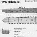 Habakkuk: how the British tried to build an aircraft carrier from ice Why the project was curtailed