Fuel combustion methods. Types of combustion devices, their characteristics. Chamber pulverized coal furnaces
The combustion device, or firebox, being the main element of the boiler unit, is designed to burn fuel in order to release the heat contained in it and obtain combustion products with the highest possible temperature. At the same time, the furnace serves as a heat exchange device, in which heat is transferred by radiation from the combustion zone to the colder surrounding heating surfaces of the boiler, as well as a device for capturing and removing some of the focal residues when burning solid fuel.
According to the method of fuel combustion, furnace devices are divided into layer and chamber. In layered furnaces, solid lump fuel is burned in a layer, in chamber furnaces - gaseous, liquid and pulverized fuels in suspension.
Modern boilers usually three main methods of solid fuel combustion are used: layer, flare, vortex.
Layer furnaces. Furnaces in which layered combustion of lumpy solid fuel is carried out are called layered. This firebox consists of a grate supporting a layer of lumpy fuel and a furnace space in which flammable volatiles are burned. Each furnace is designed to burn a specific type of fuel. The designs of the furnaces are varied, and each of them corresponds to a specific combustion method. The efficiency and economy of the boiler plant depend on the size and design of the furnace.
Layer furnaces for burning various types of solid fuel are divided into internal and external ones, with horizontal and inclined grates.
Furnaces located inside the lining of the boiler are called internal, and those located outside the lining and additionally attached to the boiler are called remote.
Depending on the method of fuel supply and the organization of maintenance, layered furnaces are subdivided into manual, semi-mechanical and mechanized.
Manual furnaces are those in which all three operations - supplying fuel to the furnace, shuraing it and removing slag (focal residues) from the furnace - are performed manually by the driver. These furnaces have a horizontal grate.
Semi-mechanical furnaces are those in which one or two operations are mechanized. These include mine ones with inclined grate grates, in which the fuel loaded into the furnace manually, as the lower layers burn out, moves along the inclined grates under the action of its own mass.
Mechanized fireboxes are those in which the supply of fuel to the confusion, its skimming and removal of focal residues from the firebox are made by a mechanical drive without manual intervention of the driver. Fuel enters the furnace in a continuous flow.
Layer furnaces for solid fuel combustion are divided into three classes:
- furnaces with a fixed grate and a layer of fuel lying on it, which include a furnace with a manual horizontal grate. All types of solid fuels can be burned on this grate, but due to manual maintenance, it is used under boilers with a steam capacity of up to 1-2 t / h. Furnaces with projectors, into which fresh fuel is continuously mechanically loaded and scattered over the grate surface, are installed under boilers with a steam capacity of up to 6.5-10 t / h;
- furnaces with a fixed grate and a layer of fuel moving along it, which include furnaces with a rustling bar and furnaces with an inclined grate. In furnaces with a rustling bar, the fuel moves along a fixed horizontal grate with a special bar of a special shape, which reciprocates along the grate. They are used for burning brown coal under boilers with a steam capacity of up to 6.5 t / h; In furnaces with an inclined grate, fresh fuel loaded into the furnace from above, as it burns under the influence of gravity, slides into the lower part of the furnace. Such furnaces are used for burning wood waste and peat under boilers with a steam capacity of up to 2.5 t / h; high-speed shaft furnaces of the V.V. Pomerantsev system are used for burning sod peat under boilers with a steam capacity of up to 6.5 t / h for burning wood waste under boilers with a steam capacity of 20 t / h;
- furnaces with moving mechanical chain grates of two types: forward and reverse. The forward-running chain grate moves from the front wall towards the rear wall of the furnace. Fuel is supplied to the grate by gravity. The return chain grate moves from the rear to the front wall of the firebox. Fuel is supplied to the Grate by a spreader. Furnaces with chain grate grates are used to burn coal, brown coal and anthracite under boilers with a steam capacity of 10 to 35 t / h.
Chamber (flare) furnaces. Chamber furnaces are used to burn solid, liquid and gaseous fuels. In this case, solid fuel must be preliminarily ground into a fine powder in special pulverizing installations - coal grinding mills, and liquid fuel must be atomized into very small droplets in fuel oil nozzles. Gaseous fuel does not require preliminary preparation.
The flare method allows burning a wide variety of low-grade fuels with high reliability and efficiency. Solid fuels in a pulverized state are burned under boilers with a steam capacity of 35 t / h and above, and liquid and gaseous fuels under boilers of any steam capacity.
Chamber (flare) furnaces are rectangular prismatic chambers made of refractory bricks or refractory concrete. The walls of the combustion chamber are covered from the inside with a system of boiling pipes - furnace water screens. They represent an effective boiler heating surface that absorbs a large amount of heat emitted by the torch, at the same time they protect the masonry of the combustion chamber from wear and tear under the action of the high temperature of the torch and molten slag.
According to the method of slag removal, flare furnaces for pulverized fuel are divided into two classes: with solid and liquid slag removal.
The furnace chamber with solid bottom ash removal has a funnel shape, called a cold funnel. Drops of slag falling out of the torch fall into this funnel, solidify due to the lower temperature in the funnel, granulate into individual grains and enter the slag receiver through the throat. The furnace chamber b with liquid slag removal is performed with a horizontal or slightly inclined hearth, which is thermally insulated in the lower part of the furnace walls to maintain a temperature exceeding the ash melting point. The molten slag that has fallen out of the torch on the bottom remains in a molten state and flows out of the furnace through the taphole into the slag-receiving bath filled with water, solidifies and cracks into small particles.
Furnaces with liquid slag removal are divided into single-chamber and two-chamber.
In two-chamber furnaces, the furnace is divided into a fuel combustion chamber and a combustion product cooling chamber. The combustion chamber is reliably covered with thermal insulation to create a maximum temperature in order to reliably obtain liquid slag. Flare furnaces for liquid and gaseous fuels are sometimes made with a horizontal or slightly inclined hearth, which is sometimes not shielded. The location of the burners in the combustion chamber is done on the front and side walls, as well as at the corners of it. Burners are available as direct-flow and swirling ones.
The method of fuel combustion is selected depending on the type and type of fuel, as well as the steam output of the boiler unit.
April 18, 2011Gaseous fuels are burned in three ways.
In the first combustion method, gas and air under low pressure are supplied simultaneously to the burner, where they are partially mixed, however, complete mixing of the gas with air is completed only at the entrance to the furnace, where the mixture burns, forming a relatively short torch. Burners that partially mix gas and air are called low pressure flame burners.
Gas enters the mixing chamber 7 in a thin annular jet. The air supplied (under a pressure slightly greater than the gas) tangentially to the body 10 by swirling jets enters the mixing chamber through the slots 8 and breaks the moving gas stream.
The gas-air mixture mixed in this way, after passing through the lined hole of the burner 9, burns in the working space of the furnace, forming a short torch.
In the second method of combustion, gas and air are fed into a special device - a mixer, in which they are completely mixed into a gas-air mixture and sent under high pressure to the burner for combustion. Combustion takes place quickly, without creating a flame in the working space of the oven.
In the third combustion method, gas is fed into the burner under high pressure, in which the required air is sucked in from the atmosphere. Mixing of gas with air takes place in an injection-type mixer built into the burner.
Burners for burning gas according to the second and third methods are called high pressure flameless burners.
"Free forging", Ya.S. Vishnevetsky

Rotary Bottom Carousel Heating Furnace Electric resistance furnaces are used to heat small billets. To heat the workpieces to a temperature of 1200-1250 ° C, furnaces with silicon carbide heaters (selite resistance elements) produced by the Electric Furnace Trust are used. Non-ferrous alloy billets are heated in furnaces with metal heaters operating at temperatures up to 900-950 ° C. These furnaces are used ...

Electrical contact heating devices are used to heat workpieces using the resistance method. 1 - generator, 2 - inductor, 3 - heated workpiece, 4 - capacitor bank, 5 - contactor. Inductors, depending on the shape and size of the heated workpiece, are: cylindrical, oval, square and slotted. The shapes of the inductors and the location of the heated workpieces in them are shown in Fig. 1 -…

Electric resistance furnace Н75 1 - heating elements, 2 - refractory masonry, 3 - thermal insulation, 4 - door lifting mechanism, 5 - counterweight, 6 - door, 7 - lift shaft, 8 - limit switch, 9 - heel bricks, 10 - hearth plate. The essence of the method consists in supplying an electric current of industrial frequency to the ends of the workpiece (or ...

The schematic electrical diagram of heating by the resistance method is shown in Fig. A large current is supplied to the workpiece clamped in the contacts with a voltage of 5.6 to 13.6 V. The current required to heat the metal increases in proportion to the square of the diameter of the workpiece. 1 - contacts, 2 - heated workpiece, 3 - supply busbars, 4 - power transformer. As…
The main indicators in assessing the operation of furnaces are: furnace productivity, specific fuel consumption and efficiency. The productivity of the furnace is the amount of metal in kilograms that can be heated in it to a given temperature per unit of time (kg / h). Productivity depends on the number of simultaneously heated workpieces, the way they are positioned on the hearth, the size of the workpiece, steel grade, temperature, heating and ...
If we take the air velocity as the defining parameter w c relative to the speed of movement of fuel particles v t, then according to this parameter four technologies of fuel combustion are distinguished.
1. In a dense filtering layer(w in >> v T).
Applies only to lumpy solid fuel that is distributed on the grate. The fuel layer is blown through with air at a rate at which the stability of the layer is not disturbed and the combustion process has an oxygen and reduction zone.
The apparent thermal stress of the grate is Q R= 1.1 ... 1.8 MW / m 2.
2. In a fluidized or fluidized bed(w in> v T).
With an increase in air speed, the dynamic head can reach and then exceed the gravitational force of the particles. The stability of the layer will be violated and a random movement of particles will begin, which will rise above the lattice, and then reciprocate up and down. The flow rate at which the stability of the layer is violated is called critical.
Its increase is possible up to the speed of particle soaring, when they are carried out by the flow of gases from the layer.
A significant part of the air passes through the fluidized bed in the form of "bubbles" (gas volumes), strongly mixing the fine-grained material of the layer, as a result, the combustion process along the height proceeds at an almost constant temperature, which ensures the completeness of fuel burnout.
A boiling fluidized bed is characterized by an air velocity of 0.5 ... 4 m / s, a fuel particle size of 3 ... 10 mm, a bed height of no more than 0.3 ... 0.5 m. Thermal stress of the furnace volume Q V= 3.0 ... 3.5 MW / m 3.
A non-combustible filler is introduced into the fluidized bed: fine quartz sand, chamotte chips, etc.
The fuel concentration in the layer does not exceed 5%, which makes it possible to burn any fuel (solid, liquid, gaseous, including combustible waste). A non-combustible filler in a fluidized bed can be active against harmful gases generated during combustion. The introduction of a filler (limestone, lime or dolomite) makes it possible to solidify up to 95% of sulfur dioxide.
3. In a stream of air(w at ≈ v t) or flare direct-flow process. Fuel particles are suspended in the gas-air flow and begin to move with it, burning during movement within the combustion chamber. The method is characterized by low intensity, extended combustion zone, sharp non-isothermality; requires a high temperature of the medium in the ignition zone and careful preparation of the fuel (spraying and premixing with air). Thermal stress of the volume of the furnace Q V≈ 0.5 MW / m 3.
Holders of the patent RU 2553748:
The invention relates to heat power engineering and can be used in furnaces and heat generators of various types that use fossil fuel for combustion.
There is a known method for efficient combustion of fuel by separating gas (combustion reaction products), for example, a Method for separating gases using membranes with permeate purging to remove CO 2 from combustion products according to patent 2489197 (RU) BAKER Richard (US), VIDZHMANS Johannes Gee (US) and others.
The implementation of this combustion method is carried out in several stages: the stage of capturing carbon dioxide, the stage of membrane separation of gases, working in combination with compression and condensation to obtain a product from carbon dioxide in the form of a liquid, and a stage based on blowing, in which incoming air or oxygen is used for the furnace. as a purge gas. The disadvantage of this method is its complexity in implementation, since it includes many additional stages of a standard type, such as heating, cooling, compression, condensation, pumping, various types of separation and / or fractionation, as well as monitoring pressures, temperatures, flows, etc. with this method, the capture of carbon dioxide occurs from the waste stream formed by the combustion of fuel diluted with ballast gases, which therefore has a lower temperature.
The closest technical solution (prototype) is a Method for burning solid fuel in household heating furnaces according to patent 2239750 (RU), the authors of Ten V.I. (RU) and Ten G.Ch. (RU), Patent holder Ten Valery Ivanovich (RU).
This method includes loading fuel onto the grate of the furnace, creating traction in its working space, igniting and burning fuel with the removal of combustion products into the atmosphere, regulating the thrust and the amount of combustion products removed from the furnace by slightly opening the blower and chimney flaps.
The disadvantage of this method of burning solid fuel is its complexity in implementation, due to the breakdown of the process into a number of separate periods, in each of which the fuel is re-ignited, brought to an intensive combustion mode, and after reaching a predetermined furnace temperature, the combustion process is transferred to a damping mode, then ignition is performed again with the help of sophisticated automation and using already liquid or gaseous fuel. The disadvantage of these and other similar methods of fuel combustion is the mixing of combustion products, heat sources (CO 2 and H 2 O), in the reaction zone, into a single flow with ballast gases (nitrogen, excess air, etc.), which worsen the conditions for fuel combustion and use of the released heat (useful heat is taken and carried out into the atmosphere).
The proposed invention aims to improve the conditions for fuel combustion and increase the amount of thermal energy released by the fuel.
The technical result of the proposed method is to increase the efficiency of furnaces and heat generators by burning combustible gases in the middle zone of the furnace bell and removing ballast gases from the combustion zone, as well as by exposing the incandescent carbon to superheated steam.
The proposed method of fuel combustion is illustrated by graphic material, where the following designations are adopted: 1 - combustion reaction zone; 2 - blower (ash pan); 3 - supply of primary air for ignition, maintenance of combustion and gasification of fuel (volatile combustible gases); 4 - combustion chamber with fuel; 5 - hydrocarbon (volatile gases); 6 - supply of secondary air to the combustion zone for burning volatile combustible gases; 7 - harmful non-combustible ballast gases that do not participate in combustion; 8 - supply of superheated steam; 9 - useful hot products - heat carriers, carbon dioxide and water vapor; 10 - heat exchange zone; 11 - grate; 12 - outlet of gases from the furnace bell.
The proposed method is carried out as follows. Solid fuel is loaded onto the grate 11, it is ignited, while the primary air enters through the blower 2 and the grate 11. Then, after ignition, secondary air 6 enters the bell directly into the combustion zone for combustion of volatile combustible gases. As a result of the combustion reaction, a mixture of unrelated gases arises: incandescent carbon dioxide and water vapor and conditionally cold ballast gases - excess air and released nitrogen in its composition (excess air with an increased nitrogen content). The peculiarity of the bell structure is that during the combustion reaction, the resulting gases are separated. Hot gases rise upward, giving off thermal energy to the bell, while cold particles of ballast gases go down through the bell zones with a low temperature. Fuel combustion reactions are expressed by well-known combustion equations. The ratios of the reacting substances are maintained, as is their composition. That is, carbon C, hydrogen H 2 with oxygen O 2 enter into the reaction in the amount determined by the chemical equations:
other substances cannot react. The combustion reaction takes place in the combustion zone between hydrocarbon and oxygen without the participation of ballast gases, while the nitrogen released from the air in the composition of excess air, as less heated, is pushed out through the lower part of the bell (the outlet pipe is not shown in the diagram). After warming up the combustion chamber and the presence of incandescent carbon in it, superheated water vapor 8 is fed into the bell below the secondary air supply zone. As a result of the interaction of carbon with water vapor at high temperatures, flammable gases arise in accordance with the well-known chemical equations

at a low temperature with a total positive thermal effect, which enhance the process of fuel combustion and increase heat transfer from it. Implementation of the proposed method of fuel combustion will increase the efficiency of furnaces and heat generators. The proposed method is quite simple to implement, does not require complex equipment and can be widely used in industry and in everyday life.
SOURCES OF INFORMATION
1. Patent of the Russian Federation No. 2489197, IPC B01D 53/22 (2006.01). Gas separation method using membranes with permeate purging to remove carbon dioxide from combustion products. Patentee, MEMBRANE TECHNOLOGY AND RESERCH, INC. (US).
2. Patent of the Russian Federation No. 2239750, IPC F24C 1/08, F24B 1/185. A method of burning fuel in household heating stoves. The patentee is Ten Valery Ivanovich.
3. Mäkelä K. Stoves and fireplaces. Reference manual. Translated from Finnish. Moscow: Stroyizdat, 1987.
4. Ginzburg D.B. Solid fuel gasification. State publishing house of literature on construction, architecture and building materials. M., 1958.
A method of fuel combustion in furnaces having a bell with a fuel combustion chamber and a grate, including loading fuel, igniting and burning fuel due to the primary air supplied through the blower, characterized in that the movement of gases in the bell is carried out without using the draft of the pipe, with the possibility of accumulating of hot gases in the upper part of the bell, while secondary air is supplied to the bell, directly to the combustion zone, while hot gases rise upward, giving thermal energy to the bell, and cold particles of ballast gases go down through the bell zones with a low temperature, after the chamber is heated combustion into it, below the secondary air supply, superheated water vapor is supplied to the incandescent carbon and combustible gases are obtained.
Similar patents:
The group of inventions relates to steam generating devices. The technical result consists in increasing the efficiency of bath procedures.
The invention relates to a cooking device for cooking food using steam. The cooking device contains a heating chamber in which food is placed and heated, a heating means that heats food, a steam-generating tank including a water-evaporation chamber, a heat source that heats a steam-generating tank, a water supply device that delivers water to the water-evaporation chamber, a supply opening for supplying steam from a water evaporation chamber, an outlet that ejects steam supplied from the supply opening into the heating chamber, a buffer chamber communicating with the supply opening and the outlet opening is located between the water evaporation chamber and the heating chamber, the heat source being located between the buffer chamber and the water evaporation chamber.
The invention relates to household appliances, namely to devices for cooking food in field conditions. A disposable camping stove includes a housing containing: a housing wall, a housing bottom, a window for igniting fuel, air windows, and the housing is made in the form of a notch made of sheet or corrugated sheet material, and the housing wall having the ability to bend and fix around the bottom of the housing has a lock latch , stops for holding the heated container and stops for holding the bottom.
The invention relates to devices for chemical laboratories, namely, desiccators - devices for slow cooling, drying and storage of substances and materials that easily absorb moisture from the air in an atmosphere with a low pressure of water vapor in sealed conditions with the simultaneous use of adsorbents.
The invention relates to the field of small-scale energy, in particular to devices for heating small private houses and sectors of low-rise buildings. The technical result is to reduce emissions of harmful substances to minimum values and increase the efficiency. The combustion device contains a body, doors for loading fuel and unloading ash, a horizontal grate and a blow channel installed in the combustion chamber of the device. The device is equipped with a vault located above the combustion chamber, a rotary chamber above the vault, upper and lower ash pans in the lower part of the body and equipped with doors, replaceable nozzles for fuel combustion located at the base of the blast channel, a horizontal grate with the ability to adjust its installation along the height of the combustion chamber ... The blast channel is located in the center of the combustion chamber and is connected to the lower ash pan, and a slope is made in the rear wall of the housing. 2 c.p. f-ly, 4 dwg.
The invention relates to heat power engineering and can be used in furnaces and heat generators of various types that use fossil fuel for combustion. The technical result is an increase in the efficiency of furnaces and heat generators. The method of fuel combustion in furnaces having a bell with a fuel combustion chamber and a grate, includes loading fuel, igniting and burning fuel due to the primary air entering through the blower. The movement of gases in the bell is carried out without using the draft of the pipe, with the possibility of accumulating hot gases in the upper part of the bell. In this case, secondary air is fed into the bell, directly into the combustion zone. Hot gases rise upward, giving off thermal energy to the bell, while cold particles of ballast gases go down through the bell zones with a low temperature. After warming up the combustion chamber, superheated water vapor is fed to the hot carbon into it, below the secondary air supply, and combustible gases are obtained. 1 ill.
 How to choose a mirrorless camera?
 Beautiful pictures with wishes of good morning, good day and mood
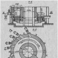 Types of combustion devices, their characteristics