The main purpose of the radar. Radar stations: history and basic principles of operation. The main indicators of the impulse method
Radar station
The radar request is redirected here; for the register of medicines, see the Register of medicines.
Radar station(Radar) or radar(eng. radar from RA dio D etection A nd R anging- radio detection and ranging) - a system for detecting air, sea and ground objects, as well as for determining their range, speed and geometric parameters. Uses a method based on the emission of radio waves and registration of their reflections from objects. The English acronym term appeared in 1941, later in its writing the uppercase letters were replaced by lowercase letters.
History
In the USSR and Russia
In the Soviet Union, the awareness of the need for aircraft detection equipment, free from the shortcomings of sound and optical surveillance, led to the development of research in the field of radar. The idea, proposed by the young artilleryman Pavel Oshchepkov, received the approval of the high command: the People's Commissar of Defense of the USSR K.E. Voroshilov and his deputy, M.N. Tukhachevsky.
In 1946, American specialists - Raymond and Hacherton, a former employee of the US Embassy in Moscow, wrote: "Soviet scientists successfully developed the theory of radar several years before radar was invented in England."
Classification
According to the scope of application, there are- military;
- civil;
- Radar detection;
- Radar control and tracking;
- Panoramic radar;
- Side-looking radar;
- Meteorological radar;
- Target designation radar;
- Surveillance radar;
- Coastal radar
- Marine radar
- Onboard radar
- Mobile radars
- Primary or passive
- Secondary or active
- Combined
- Over-the-horizon radar
- Meter
- Decimeter
- Centimeter
- Millimeter
Design and principle of operation of the Primary radar
Primary (passive) radar is mainly used to detect targets by illuminating them with an electromagnetic wave and then receiving reflections (echo) of this wave from the target. Since the speed of electromagnetic waves is constant (speed of light), it becomes possible to determine the distance to a target based on measurements of various signal propagation parameters.
At the heart of a radar device are three components: a transmitter, an antenna, and a receiver.
Transmitter(transmitter) is a high power electromagnetic signal source. It can be a powerful pulse generator. For pulsed radars of the centimeter range, usually a magnetron or a pulse generator operating according to the scheme: master oscillator is a powerful amplifier that most often uses a traveling wave tube as a generator, and for a meter range radar, a triode lamp is often used. Depending on the design, the transmitter works either in a pulsed mode, generating repetitive short powerful electromagnetic pulses, or emits a continuous electromagnetic signal.
Antenna performs the focusing of the transmitter signal and the formation of the directional diagram, as well as receiving the signal reflected from the target and transmitting this signal to the receiver. Depending on the implementation, the reception of the reflected signal can be carried out either by the same antenna or by another, which can sometimes be located at a considerable distance from the transmitting device. In the event that transmission and reception are combined in one antenna, these two actions are performed alternately, and so that a powerful signal leaking from the transmitting transmitter into the receiver does not blind the receiver of a weak echo, a special device is placed in front of the receiver that closes the receiver input at the time of the probe signal emission.
Receiver(receiving device) performs amplification and processing of the received signal. In the simplest case, the resulting signal is applied to a ray tube (screen), which shows an image synchronized with the movement of the antenna.
Different radars are based on different echo measurement methods:
Frequency method
The frequency-based ranging method is based on the use of frequency modulation of the emitted continuous signals. In this method, a frequency is emitted over a period that varies according to a linear law from f1 to f2. The reflected signal will arrive linearly modulated at the time before the present by the delay time. That. the frequency of the reflected signal received by the radar will proportionally depend on time. The lag time is determined by the sharp change in the frequency of the difference signal.
Advantages:
- allows you to measure very short ranges;
- a low-power transmitter is used;
Flaws:
- requires the use of two antennas;
- deterioration of the receiver sensitivity due to leakage through the antenna into the receiving path of the transmitter radiation, which is subject to random changes;
- high requirements for the linearity of the frequency change;
These are its main disadvantages.
Phase method
The phase (coherent) method of radar is based on the extraction and analysis of the phase difference between the sent and reflected signals, which occurs due to the Doppler effect, when the signal is reflected from a moving object. In this case, the transmitting device can operate both continuously and in a pulsed mode. The main advantage of this method is that it "allows you to observe only moving objects, and this eliminates interference from stationary objects located between the receiving equipment and the target or behind it."
Since ultrashort waves are used in this case, the unambiguous range of range measurement is of the order of a few meters. Therefore, in practice, more complex circuits are used, in which there are two or more frequencies.
Advantages:
- low-power radiation, since sustained oscillations are generated;
- the accuracy is independent of the Doppler shift of the reflection frequency;
- a fairly simple device;
Flaws:
- lack of range resolution;
- deterioration of the receiver sensitivity due to penetration through the antenna into the receiving path of the transmitter radiation, which is subject to random changes;
Pulse method
Modern tracking radars are built like pulse radars. Pulse radar transmits an emitting signal only for a very short time, with a short pulse (usually about a microsecond), after which it switches to receive mode and listens to the echo reflected from the target, while the emitted pulse propagates through space.
Since the pulse travels far from the radar at a constant speed, the time elapsed from the moment the pulse was sent to the moment the echo response was received is a direct dependence of the distance to the target. The next pulse can be sent only after some time, namely after the pulse comes back (it depends on the radar detection range, transmitter power, antenna gain, receiver sensitivity). If the pulse is sent earlier, the echo of the previous pulse from a distant target can be confused with the echo of the second pulse from a nearby target.
The time interval between impulses is called pulse repetition interval, its reciprocal is an important parameter that is called pulse repetition rate(CPI). Low frequency long range radars typically have a repetition rate of several hundred pulses per second. The pulse repetition rate is one of the distinguishing features by which remote detection of the radar model is possible.
Advantages of the pulsed range measurement method:
- the ability to build a radar with one antenna;
- simplicity of the indicator device;
- convenience of measuring the range of several targets;
- the simplicity of the pulses emitted, lasting a very short time, and the signals received;
Flaws:
- The need to use high pulse powers of the transmitter;
- impossibility of measuring short ranges;
- large dead zone;
Elimination of passive interference
One of the main problems of impulse radars is getting rid of the signal reflected from stationary objects: the earth's surface, high hills, etc. If, for example, an airplane is in the background of a high hill, the reflected signal from this hill will completely block the signal from the airplane. For ground-based radars, this problem manifests itself when working with low-flying objects. For on-board pulse radars, it is expressed in the fact that the reflection from the earth's surface obscures all objects lying below the aircraft with the radar.
Interference elimination methods use, one way or another, the Doppler effect (the frequency of a wave reflected from an approaching object increases, from an outgoing object it decreases).
The simplest radar that can detect a target in jamming is moving target radar(SDC) - Pulse radar that compares reflections from more than two or more pulse repetition intervals. Any target that moves relative to the radar produces a change in the signal parameter (stage in the serial SDC), while the interference remains unchanged. Elimination of noise occurs by subtracting reflections from two consecutive intervals. In practice, the elimination of interference can be carried out in special devices - through periodical compensators or algorithms in software.
SDCs operating at a constant pulse repetition rate have a fundamental weakness: they are blind to targets with specific rotational speeds (which produce phase changes of exactly 360 degrees), and such targets are not displayed. The rate at which the target disappears for the radar depends on the operating frequency of the station and on the pulse repetition rate. Modern SDCs emit multiple pulses at different repetition rates - such that invisible speeds at each pulse repetition rate are encompassed by other PRFs.
Another way to get rid of interference is implemented in pulse-Doppler radar which use significantly more sophisticated processing than radar with SDC.
An important property of Pulse Doppler radars is signal coherence. This means that the sent signals and reflections must have a certain phase dependence.
Pulse Doppler radars are generally considered superior to SDC radars for detecting low-flying targets in multiple ground clutter, and are the preferred technique used in modern fighter aircraft for air interception / fire control (examples are AN / APG-63, 65, 66, 67 and 70 radars). In modern Doppler radar, most of the processing is done in a separate digital processor using digital signal processors, usually using the high-performance Fast Fourier Transform algorithm to transform the digital data of the reflection samples into something more controlled by other algorithms. Digital signal processors are very flexible, since the algorithms used in them can be quickly replaced by others, by changing only the program in the device memory ("firmware" of the ROM), thus, if necessary, quickly adapting to the enemy jamming technique.
Radar ranges
| Range | Etymology | Frequencies | Wavelength | Notes (edit) |
|---|---|---|---|---|
| HF | English high frequency | 3-30 MHz | 10-100 m | Coast Guard radars, over-the-horizon radars |
| P | English previous | < 300 МГц | > 1 m | Used in early radars |
| VHF | English very high frequency | 50-330 MHz | 0.9-6 m | Long range detection, Earth exploration |
| UHF | English ultra high frequency | 300-1000 MHz | 0.3-1 m | Long range detection (e.g. artillery fire), forest exploration, Earth surface |
| L | English Long | 1-2 GHz | 15-30 cm | surveillance and air traffic control |
| S | English Short | 2-4 GHz | 7.5-15 cm | air traffic control, meteorology, maritime radars |
| C | English Compromise | 4-8 GHz | 3.75-7.5cm | meteorology, satellite broadcasting, intermediate range between X and S |
| X | 8-12 GHz | 2.5-3.75 cm | weapon control, missile guidance, maritime radars, weather, medium resolution mapping; in the USA, the 10.525 GHz ± 25 MHz band is used in airport radars | |
| K u | English under K | 12-18 GHz | 1.67-2.5cm | high resolution mapping, satellite altimetry |
| K | German kurz- "short" | 18-27 GHz | 1.11-1.67 cm | use is limited due to strong absorption by water vapor, therefore the K u and K a ranges are used. The K-band is used for cloud detection in police road radars (24.150 ± 0.100 GHz). |
| K a | English above K | 27-40 GHz | 0.75-1.11 cm | Mapping, short range air traffic control, special radars driving road cameras (34.300 ± 0.100 GHz) |
| mm | 40-300 GHz | 1-7.5 mm | millimeter waves are divided into the following two ranges | |
| V | 40-75 GHz | 4.0-7.5mm | EHF medical devices used for physiotherapy | |
| W | 75-110 GHz | 2.7-4.0mm | sensors in experimental automatic vehicles, high-precision studies of weather phenomena |
Secondary radar
Secondary radar is used in aviation to identify aircraft. The main feature is the use of an active transponder on airplanes.
The principle of operation of the secondary radar is somewhat different from that of the Primary radar. The device of the Secondary radar station is based on the components: a transmitter, an antenna, azimuth mark generators, a receiver, a signal processor, an indicator and an aircraft transponder with an antenna.
Transmitter- serves to emit request pulses into the antenna at a frequency of 1030 MHz
Antenna- serves for the emission and reception of the reflected signal. According to ICAO standards for secondary radar, the antenna radiates at 1030 MHz and receives at 1090 MHz.
Azimuth mark generators- serve to generate azimuth marks (Azimuth change pulse or ACP) and generation North marks (Azimuth Reference Pulse or ARP). In one revolution of the radar antenna, 4096 small azimuth marks (for old systems) or 16384 small azimuth marks (for new systems, also called Improved Azimuth Change pulse or IACP), as well as one North marker are generated. from the generator of azimuth marks at this position of the antenna, when it is directed to the North, and small azimuth marks are used to read the angle of rotation of the antenna.
Receiver- serves to receive pulses at a frequency of 1090 MHz.
Signal processor- serves to process the received signals.
Indicator- serves to indicate processed information.
Aircraft transponder with antenna- serves to transmit a pulsed radio signal containing additional information back to the radar when receiving a request radio signal.
The principle of the secondary radar is to use the energy of the aircraft transponder to determine the position of the aircraft. The radar irradiates the surrounding space with interrogation pulses at frequencies P1 and P3, as well as a suppression pulse P2 at a frequency of 1030 MHz. Aircraft equipped with transponders, which are in the range of the interrogation beam, upon receiving interrogation pulses, if the condition P1 is valid, P3> P2, they respond to the interrogating radar with a series of coded pulses at a frequency of 1090 MHz, which contain additional information about the side number, altitude, and so on ... The response of the aircraft transponder depends on the radar request mode, and the request mode is determined by the time interval between the P1 and P3 request pulses, for example, in the A request mode (mode A), the time interval between the P1 and P3 request pulses is 8 microseconds, and when such a request is received, the responder the aircraft encodes its aircraft number in response pulses.
In interrogation mode C (mode C), the time interval between interrogation pulses of the station is 21 microseconds, and upon receipt of such a request, the aircraft responder encodes its height in response pulses. Also, the radar can send a request in a mixed mode, for example, Mode A, Mode C, Mode A, Mode C. The azimuth of the aircraft is determined by the antenna rotation angle, which in turn is determined by calculating small azimuth marks.
The range is determined by the delay in the received response. If the aircraft is in the coverage area of the side lobes, and not the main beam, or is behind the antenna, then the responder of the aircraft, upon receiving a request from the radar, will receive at its input the condition that the pulses P1, P3 The signal received from the transponder is processed by the radar receiver, then goes to the signal processor, which processes the signals and provides information to the end user and (or) to the control indicator. Pros of secondary radar: The article discusses the principle of operation and the general structural diagram of the ship's radar. The operation of radar stations (radar) is based on the use of the phenomenon of reflection of radio waves from various obstacles located in the path of their propagation, i.e., in radar, the phenomenon of echo is used to determine the position of objects. For this, the radar has a transmitter, a receiver, a special antenna-waveguide device and an indicator with a screen for visual observation of echo signals. Thus, the operation of a radar station can be represented as follows: a radar transmitter generates high-frequency oscillations of a certain shape, which are sent into space by a narrow beam that continuously rotates along the horizon. Reflected vibrations from any object in the form of an echo signal are received by the receiver and displayed on the indicator screen, while it is possible to immediately determine on the screen the direction (bearing) to the object and its distance from the vessel. The magnetron generates a probing pulse with a power of 70-80 kW, wavelength 1 = 3.2 cm, frequency / s = 9400 MHz. The impulse of the magnetron is fed to the antenna through an antenna switch (AP) through a special waveguide and is emitted into space by a narrow directional beam. The beam width in the horizontal plane is 1-2 °, and the vertical one is about 20 °. The antenna, rotating around the vertical axis at a speed of 12-30 rpm, irradiates the entire space surrounding the vessel. Good evening everyone :) I was surfing the Internet after visiting a military unit with a considerable number of radar stations. Radar stations P-15 and P-19
The P-15 station is mounted on one vehicle together with the antenna system and is deployed into a combat position in 10 minutes. The power unit is transported in a trailer. The station has three operating modes: The first car is equipped with transmitting and receiving equipment, anti-jamming equipment, indicator equipment, equipment for transmitting radar information, simulating, communicating and interfacing with consumers of radar information, functional control and equipment for a ground-based radar interrogator. The second car is equipped with an antenna-rotary radar device and power supply units. Difficult climatic conditions and the duration of operation of the P-15 and P-19 radars have led to the fact that by now most of the radars require resource restoration. The only way out of this situation is considered to be the modernization of the old radar fleet based on the Kakta-2E1 radar. The modernization proposals took into account the following: Maintaining intact the main radar systems (antenna system, antenna rotation drive, microwave path, power supply system, vehicles); Possibility of modernization in operating conditions with minimal financial costs; Possibility of using the released P-19 radar equipment to restore products that have not been upgraded. As a result of the modernization, the P-19 mobile solid-state low-altitude radar will be able to perform the tasks of airspace monitoring, determining the range and azimuth of air objects - aircraft, helicopters, remotely piloted aircraft and cruise missiles, including those operating at low and extremely low altitudes, at the background of intense reflections from the underlying surface, local objects and hydrometeorological formations. The radar is easily adaptable to use in various military and civilian systems. It can be used for information support of air defense systems, air forces, coastal defense systems, rapid reaction forces, civil aviation aircraft traffic control systems. In addition to the traditional use as a means of detecting low-flying targets in the interests of the armed forces, the modernized radar can be used to control the airspace in order to prevent the transportation of weapons and drugs by low-altitude, low-speed and small aircraft in the interests of special services and police units involved in combating drug trafficking and arms smuggling. ... Upgraded radar station P-18
As a result of modernization: Radar complex P-40A
Radar rangefinder 1RL128 "Bronya" is a radar of all-round visibility and together with radar altimeter 1RL132 forms a three-coordinate radar complex P-40A. The radar complex is part of the radio-technical formations and air defense formations, as well as anti-aircraft missile (artillery) units and formations of the military air defense. "Sky-SV" two-coordinate standby radar
Mobile three-coordinate radar station 9С18М1 "Kupol"
The 9S18M1 radar is a three-coordinate coherent-pulse station for detection and target designation, using long-duration probing pulses, which provides high energy of the emitted signals. The radar is equipped with digital equipment for automatic and semi-automatic acquisition of coordinates and equipment for identifying detected targets. The entire process of radar operation is maximally automated thanks to the use of high-speed computing electronic means. To improve the efficiency of work in conditions of active and passive interference, the radar uses modern methods and means of anti-jamming. The 9S18M1 radar is located on a high-cross-country tracked chassis and is equipped with an autonomous power supply system, navigation, orientation and topography equipment, telecode and voice radio communications. In addition, the radar has a built-in automated functional control system, which provides a quick search for a faulty replaceable element and a simulator for processing the skills of the operators. To transfer them from the traveling position to the combat position and vice versa, devices for automatic deployment and folding of the station are used. Air Defense Air Force The radar is located on six transport units (two semi-trailers with equipment, two with an antenna-mast device and two trailers with a power supply system). A separate semitrailer has a remote post with two indicators. It can be removed from the station at a distance of up to 1 km. To identify air targets, the radar is equipped with a ground radio transmitter. The station uses a folding design of the antenna system, which made it possible to significantly reduce the time of its deployment. Protection against active noise interference is provided by tuning the operating frequency and a three-channel auto-compensation system, which automatically forms "zeros" in the antenna directional pattern in the direction of the jammers. To protect against passive interference, coherent compensation equipment based on potentioscopic tubes was used. The station provides three modes of viewing space: - "lower beam" - with an increased target detection range at low and medium altitudes; - "upper beam" - with an increased upper limit of the detection area in elevation; Scanning - with alternate (through the review) the inclusion of the upper and lower beams. The station can be operated at an ambient temperature of ± 50 ° С, wind speed up to 30 m / s. Many of these stations were exported and are still in operation in the military. Radar "Oborona-14" can be upgraded on a modern element base using solid-state transmitters and a digital information processing system. The developed installation kit of the equipment makes it possible, directly at the customer's position, to perform work on the modernization of the radar in a short time, to bring its characteristics closer to the characteristics of modern radars, and to extend the service life by 12-15 years at costs several times less than when purchasing a new station. The "Sky" all-round radar is located on eight transport units (on three semi-trailers - an antenna-mast device, on two - equipment, on three trailers - an autonomous power supply system). There is a portable device transported in container boxes. The radar operates in the meter wavelength range and combines the functions of a rangefinder and an altimeter. In this range of radio waves, the radar is hardly vulnerable to homing shells and anti-radar missiles operating in other ranges, and these weapons are currently absent in the operating range. In the vertical plane, electronic scanning with an altimeter beam in each element of the range resolution is implemented (without the use of phase shifters). Noise immunity in conditions of active interference is provided by adaptive tuning of the operating frequency and a multichannel auto-compensation system. The passive interference protection system is also based on correlation autocompensators. For the first time, to ensure noise immunity in the presence of combined interference, the space-time isolation of protection systems against active and passive interference has been implemented. Measurement and delivery of coordinates are carried out using auto-pickup equipment based on a built-in special calculator. There is an automated control and diagnostics system. The transmitting device is distinguished by high reliability, which is achieved due to one hundred percent redundancy of a powerful amplifier and the use of a group solid-state modulator. The 1L117M radar is an improved modification of the previous 1L117 model. The main difference of the improved radar is the use of a klystron output power amplifier of the transmitter, which made it possible to increase the stability of the radiated signals and, accordingly, the coefficient of suppression of passive interference and improve the characteristics of low-flying targets. In addition, due to the presence of frequency tuning, the characteristics of the radar operation in jamming conditions are improved. In the device for processing radar data, new types of signal processors are used, the system of remote control, monitoring and diagnostics has been improved. The basic set of radar 1L117M includes: Machine No. 1 (transceiver) consists of: lower and upper antenna systems, a four-channel waveguide path with transmitting and receiving equipment PRL and state identification equipment; Machine No. 2 has a pickup cabinet (point) and an information processing cabinet, a radar indicator with remote control; Vehicle No. 3 transports two diesel power plants (main and backup) and a set of radar cables; Machines # 4 and # 5 contain auxiliary equipment (spare parts, cables, connectors, mounting kit, etc.). They are also used to transport a disassembled antenna system. Survey of space is provided by mechanical rotation of the antenna system, which forms a V-shaped directional pattern, consisting of two beams, one of which is located in the vertical plane, and the other in a plane located at an angle of 45 to the vertical. Each radiation pattern, in turn, is formed by two beams formed at different carrier frequencies and having orthogonal polarization. The radar transmitter generates two sequential phase-shift keying pulses at different frequencies, which are sent to the feeds of the vertical and inclined antennas through the waveguide path. The receiving system and digital equipment of the SDC provide reception and processing of target echo signals against the background of natural interference and meteorological formations. The radar processes echoes in a "moving window" with a fixed false alarm rate and has interscope processing to improve target detection in the presence of interference. The SDC equipment has four independent channels (one for each receiving channel), each of which consists of coherent and amplitude parts. The output signals of the four channels are combined in pairs, as a result of which the normalized amplitude and coherent signals of the vertical and oblique beams are supplied to the radar extractor. The information pickup and processing cabinet receives data from the PLR and state identification equipment, as well as rotation and synchronization signals, and provides: the choice of an amplitude or coherent channel in accordance with the information of the interference map; secondary processing of radar data with the construction of trajectories according to radar data, combining the marks of the radar and state identification equipment, displaying the air situation on the screen with forms "tied" to targets; extrapolation of target location and collision prediction; introduction and display of graphic information; control of the mode of recognition; solution of guidance (interception) tasks; analysis and display of meteorological data; statistical assessment of the radar operation; generation and transmission of exchange messages to control points. Distinctive features of the station: Thank you all for your attention :) The principle of operation of a pulsed radar can be understood by considering the "Simplified block diagram of a pulsed radar (Fig. 3.1, slide 20, 25
) and graphs explaining the operation of a pulsed radar (Fig.3.2, slide 21, 26
). It is best to begin to consider the operation of a pulsed radar from the synchronization unit (launch unit) of the station. This block sets the "rhythm" of the station operation: it sets the repetition rate of the probing signals, synchronizes the operation of the indicator device with the operation of the station transmitter. The synchronizer generates short-term sharp-pointed impulses AND zap with a certain repetition rate T NS... Structurally, the synchronizer can be made in the form of a separate unit or represent a single whole with the station modulator. Modulator
controls the operation of the microwave generator, turns it on and off. The modulator is triggered by synchronizer pulses and generates powerful rectangular pulses of the required amplitude U m and duration τ
and... The microwave generator is switched on only in the presence of modulator pulses. The frequency of switching on the microwave generator, and, consequently, the repetition rate of the probing pulses is determined by the frequency of the synchronizer pulses T NS... The duration of the microwave generator each time it is turned on (that is, the duration of the probe pulse) depends on the duration of the pulse shaping in the modulator τ
and... Modulator pulse duration τ
and usually it is a few microseconds, and the pauses between them are hundreds and thousands of microseconds. Under the action of the modulator voltage, the microwave generator generates powerful radio pulses U gene, the duration and shape of which is determined by the duration and shape of the modulator pulses. High-frequency oscillations, that is, probing pulses from the microwave generator, go through the antenna switch to the antenna. The frequency of oscillations of radio pulses is determined by the parameters of the microwave generator. Antenna switch
(AP) provides the ability to operate the transmitter and receiver on one common antenna. During the generation of the probe pulse (μs), it connects the antenna to the transmitter output and blocks the receiver input, and for the rest of the time (the pause time is hundreds, thousands of μs), it connects the antenna to the receiver input and disconnects it from the transmitter. In a pulse radar, automatic high-speed switches are used as antenna switches. The antenna converts microwave oscillations into electromagnetic energy (radio waves) and focuses it into a narrow beam. Signals reflected from the target are received by the antenna, pass through the antenna switch and enter the receiver input U with, where they are selected, amplified, detected and fed through the anti-interference equipment to the indicating devices. The anti-jamming equipment is switched on only if there is passive and active interference in the radar coverage area. This equipment will be studied in detail in topic 7. The display device is a terminal device of the radar and serves to display and retrieve radar information. The electrical circuit and design of the indicating devices are determined by the practical purpose of the station and can be very different. For example, for radar detection with the help of indicator devices, the air situation should be reproduced and the coordinates of targets D and β should be determined. These indicators are called all-round view indicators (PIDs). Altitude indicators are used in the radar for measuring the altitude of the target (altimeters). Range indicators measure only the range to the target and are used for control. To accurately determine the range, it is necessary to measure the time interval t s(tens and hundreds of microseconds) with high accuracy, that is, devices with very low inertia are required. Therefore, in the range indicators, cathode-ray tubes (CRT) are used as measuring devices. Note.
The principle of measuring the range was studied in lesson 1, therefore, when studying this issue, the main attention should be paid to the formation of the sweep on the PPI. The essence of ranging (lag time t s) using a CRT can be explained by the example of using a linear sweep in a tube with an electrostatic electron beam. With a linear scan in a CRT, an electron beam under the action of a scan voltage U R periodically moves at a constant speed in a straight line from left to right (Fig. 1.7, slide 9, 12
). The sweep voltage is generated by a special sweep generator, which is triggered by the same synchronizer pulse as the transmitter modulator. Therefore, the movement of the beam across the screen begins each time the probe pulse is sent. When using the amplitude mark of the target, the reflected signal coming from the output of the receiver causes the beam to be deflected in the perpendicular direction. Thus, the reflected signal can be seen on the screen of the tube. The further the target is, the more time passes before the appearance of the reflected pulse and further to the right the beam manages to move along the sweep line. Obviously, each point of the scan line corresponds to a certain moment of arrival of the reflected signal and, therefore, a certain value of the range. The radars operating in the circular view mode use circular view indicators (ICO) and CRT with electromagnetic beam deflection and brightness mark. The radar antenna with a narrow beam (BP) is moved by the antenna rotation mechanism in the horizontal plane and "scans" the surrounding space (Fig. 3.3, slide, On the PPI, the range sweep line rotates in azimuth synchronously with the antenna, and the beginning of the movement of the electron beam from the center of the tube in the radial direction coincides with the instant of emission of the probe pulse. Synchronous rotation of the sweep on the IKO with the radar antenna is carried out using a power synchronous drive (SSP). The response signals are displayed on the indicator screen in the form of a brightness mark. ICO allows you to simultaneously determine the range D and azimuth β
goals. For the convenience of readout, scale marks of range are electronically applied on the screen of the PPI, which have the form of circles and scale marks of azimuth in the form of bright radial lines (Fig. 3.3, slide, 8, 27
). Note.
Using a television set and a TV card, invite students to determine the coordinates of the goals. Indicate the scale of the indicator: range marks follow after 10 km, azimuth marks - after 10 degrees. CONCLUSION (slide 28)
Determining the distance to an object with the impulse method is reduced to measuring the delay time t s
the reflected signal relative to the probe pulse. The moment of emission of the probe pulse is taken as the origin of the time of propagation of radio waves. Advantages of pulse radars: convenience of visual observation of all targets simultaneously irradiated by the antenna in the form of marks on the indicator screen; alternating operation of the transmitter and receiver allows the use of one common antenna for transmission and reception. Second training question.
The main indicators of the impulse method The main indicators of the impulse method are (slide 29)
: Unambiguously determined maximum range, D; range resolution, δД; minimum detectable range, D min . Let's consider these indicators. Unambiguous maximum range
The maximum range of the radar is determined by the basic radar formula and depends on the radar parameters. The unambiguity of determining the distance to the object depends on the repetition period of the probing pulses T NS... Further, this question is stated as follows. The maximum range of the radar is 300 km. Determine the delay time to the target located at this range The repetition period of the probing pulses was chosen equal to 1000 μs. Determine the range to the target, the delay time to which is T NS There are two targets in the airspace: target No. 1 at a distance of 100 km and target No. 2 at a distance of 200 km. How will the marks from these targets look like on the radar indicator (Fig. 3.4, slide 22, 30
). When probing space with pulses with a repetition period of 1000 μs, the mark from target No. 1 will be displayed at a distance of 50 km, since after a range of 150 km a new sweep period will begin and the distant target will mark at the beginning of the scale (at a distance of 50 km). The counted range does not correspond to the real one. How to eliminate ambiguity in determining the range? After summarizing the students' answers, conclude: For an unambiguous determination of the range, it is necessary to select the repetition period of the sounding pulses in accordance with the specified maximum range of the radar, that is For a given range of 300 km, the repetition period of the sounding pulses must be greater than 2000 μs or the repetition frequency must be less than 500 Hz. In addition, the maximum detectable range depends on the width of the antenna beam, the speed of rotation of the antenna, and the required number of pulses reflected from the target during one rotation of the antenna. Range resolution (δD) is the minimum distance between two targets located at the same azimuth and elevation, at which the signals reflected from them are observed on the indicator screen separately.(Fig.3.5, slide 23, 31,
32
). For a given duration of the probing pulse τ
and and distance between targets ∆Д 1
targets # 1 and # 2 are irradiated separately. With the same pulse width, but with a distance between targets ∆Д 2
targets no. 3 and no. 4 are irradiated simultaneously. Consequently, in the first case, the PPIs will be visible on the screen separately, and in the second - together. From this it follows that for the separate reception of pulse signals, it is necessary that the time interval between the moments of their reception be greater than the pulse duration τ
and (∆
t
> τ
and )
Minimum difference (D
2
- D
1
), at which targets are visible on the screen separately, by definition there is a range resolution δD,
Consequently In addition to the pulse duration
τ
and the resolution of the station in terms of range is influenced by the resolution of the indicator, which is determined by the sweep scale and the minimum diameter of the glowing spot on the CRT screen ( d NS
≈
1 mm). The larger the range sweep scale and the better the focusing of the CRT beam, the better the resolution of the indicator. In the general case, the range resolution of the radar is where δД and- the resolution of the indicator. The less δД
, the better the resolution. Typically, the radar range resolution is
δД= (0.5 ... 5) km. Unlike the range resolution, the angular resolution (azimuth δβ
and the corner of the place
δε
) not
depends
from the radar method and is determined by the width of the antenna radiation pattern in the corresponding plane, which is usually measured at the half power level. Radar azimuth resolution
δβ
O is equal to: δβ
O = φ
0.5r
O
+ δβ
and O , where φ
0.5r
O- width of the directional pattern at half power in the horizontal plane; δβ
and O- azimuth resolution of the indicator equipment. High-resolution radar stations allow you to separately observe and determine the coordinates of closely spaced targets. The minimum detectable range is the shortest distance at which the station can still detect a target. Sometimes the area around the station, in which targets are not detected, is called a "dead" zone.
( slide 33
). The use of one antenna in a pulsed radar for transmitting sounding pulses and receiving reflected signals requires turning off the receiver for the duration of the radiation of the sounding pulse. τ
u... Therefore, the reflected signals arriving at the station at the moment when its receiver is not connected to the antenna will not be received and registered on the indicators. The length of time during which the receiver cannot receive reflected signals is determined by the duration of the probe pulse τ
u and the time required to switch the antenna from transmitting to receiving after exposure to the probe pulse of the transmitter t in . Knowing this time, the value of the minimum range D min
pulse radar can be determined by the formula where τ
u- the duration of the radar probe pulse; t in- time of switching on the receiver after the end of the probe pulse of the transmitter (units - μs). For example... At τ
u= 10μs
D min
= 1500 m at τ
u= 1 μs D min
= 150 m. It should be borne in mind that to increase the radius of the "dead" zone D min
leads to the presence on the screen of the indicator reflected from local objects and the limited range of rotation of the antenna in elevation. CONCLUSION The pulsed radar method is effective for measuring the range of objects located at great distances. Third study question
Continuous radiation method Along with the use of the pulsed method, radar can be carried out using installations with continuous energy radiation. With the continuous method of radiation, it is possible to send more energy towards the target. Along with the advantage of the energy order, the method of continuous radiation is inferior to the pulsed method in a number of indicators. Depending on which parameter of the reflected signal serves as the basis for measuring the range to the target, with the continuous method of radar, they are distinguished: phase (phasometric) method of radar; frequency method of radar. Combined methods of radar are also possible, in particular, pulse-phase and pulse-frequency. With the phase method
For radar, the distance from the target to the target is judged by the phase difference between the emitted and received reflected vibrations. The first phasometric distance measurement methods were proposed and developed by academicians L.I. Mandelstam and N.D. Papaleksi. These methods have found application in long-wave long-range aviation radio navigation systems. With the frequency method
For radar, the distance to the target is judged by the beat frequency between the direct and reflected signals. Note.
Students study these methods independently. Literature: Slutsky V.Z. Pulse technique and fundamentals of radar. S. 227-236. CONCLUSION Determination of the distance to the object with the pulse method is reduced to changing the delay time t zap of the reflected signal relative to the probing pulse. For unambiguous determination of the distance to the object, it is necessary that t zap.mah ≤ T p. The range resolution δД is the better, the shorter the duration of the probe pulse τ u. Types of radar. In radar systems, active, active with an active response and passive radar are used. Active radar (Fig. 2.1, a) assumes that the detected object located at point O is not a source of radio signals. In such a radar, the transmitter generates a sounding signal, and the antenna irradiates the target in the process of scanning the space. The receiver (Rm) amplifies and converts the reflected signal received from the target and sends it to the output device that solves the problem of detecting and measuring the coordinates of the object. Active radar with an active response (Fig. 2.1, b) implements the request-response principle and differs in that the detected object is equipped with a responder. The interrogator's transmitter generates the interrogator signal, and the interrogator's antenna irradiates the object equipped with the transponder during the space survey. The latter receives the request signal and sends a response signal to. Having received and detected this signal, the interrogator uses the output device to find the coordinates of the object equipped with the responder. In such systems, coded request and response are possible, which increases the noise immunity of the information transmission line. In addition, additional information can be transmitted over the interrogator-responder line. Since the object is active (there is a transmitter, the range of the radar is increased compared to the range of a conventional active radar system, but the radar becomes more complicated (sometimes this type of radar is called secondary radar). Passive radar solves the problem of detecting an active object emitting radio waves (Fig. 2.1, c). With passive target detection, two situations are possible: when there is a radio transmitter on the detected object, the signals of which are captured by a passive radar, and when natural radiation of a passive object in the radio or infrared wavelength range is received, which occurs when the object temperature is above absolute zero and when the temperature contrast with surrounding objects ... This type of radar is simple and highly immune to interference. Rice. 2.1. Structural diagrams of radar options Types of radar systems. By the nature of the placement of parts of the equipment in space, one-position, two-position (bistatic) and multi-position radars are distinguished. The last two types of radars are distinguished by the fact that their equipment is spaced apart in space and these radars can function both independently and jointly (spaced radar). Due to the spatial separation of elements in such systems, greater information content and noise immunity are achieved, but the system itself becomes more complex. Single-position radar systems (OPRS) differ in that all equipment is located in one position. In what follows we will denote such radar systems. The OPRS implements an active or passive type of radar (see Fig. 2.1, a - c). With active radar with an active response, the interrogator's equipment is located at one point in space, and the transponder - at another. Depending on the purpose of the radar and the type of signals used, the structural diagrams of the OPRS can be specified and, at the same time, significantly differ from each other. Let us consider, as an example, the operation of a pulsed active radar for detecting air targets for air traffic control (ATC), the structure of which is shown in Fig. 2.2, and the appearance in Fig. 2.3. The view control device (antenna control) is used to view space (usually a circular) antenna beam, narrow in the horizontal plane and wide in the vertical one. In the OPRLS under consideration, a pulsed radiation mode is used, therefore, at the end of the next sounding radio pulse, the only antenna switches from the transmitter to the receiver and is used for receiving until the next sounding radio pulse starts to be generated, after which the antenna is reconnected to the transmitter, etc. Rice. 2.2. Block diagram of the radar for detecting air targets This operation is performed by a transmit-receive switch (RFP). Trigger pulses that set the repetition period of the probing signals and synchronize the operation of all ORLS subsystems are generated by the synchronizer (Synch). The signal from the receiver (PRM) after the analog-to-digital converter ADC goes to the information processing equipment - the signal processor, where the primary information processing is performed, which consists in detecting the signal and measuring the coordinates of the target. Target marks and trajectory traces are formed during the secondary processing of information in the data processor. Rice. 2.3. Dnepr ATC surveillance radar The generated signals, together with information about the angular position of the antenna, are transmitted for further processing to the command post, as well as for monitoring the circular view indicator (IKO). With autonomous operation of the radar, the IKO serves as the main element for observing the air situation. Such a radar usually processes information in digital form. For this, a signal-to-digital code conversion device (ADC) is provided. Bistatic radar systems (BiRLS) are radars in which the transmitting and receiving parts are located at different points in space (see Fig. 2.1, d). Such biradars are based on the active type of radar.see also
Literature
Articles Links
Notes (edit)
Soviet and Russian radar stations
Radar Station of the Radio Engineering Troops
"RUS-1" "RUS-2" "P-3""P-8" Volga "" "P-10" Volga-A """P-14" "P-18" Terek "" "P-20" "P-30" "P-35" Drainage "" "P-37" "P-40" "P-70" Lena-M " "" Resonance-N (E) "" Ring "" Casta " "5N59.19Zh6.35D6 / 36D6""Casta-2E" "Gamma-C1E" "Gamma-DE" "Defense-14""5N87" "Desna-M" "Opponent-GE"
Radio altimeters
"PRV-9" "PRV-10" "PRV-11" "PRV-13" "PRV-16""PRV-17"
Special radar air defense systems
P-15 P-19 1L117M Desna-M 76N6 96L6E
Long-range radar stations
Dnieper Dniester-M Darial Krona Danube Don-2N Duga 1 Volga Voronezh-M / DM Vitim
Aircraft radar
Gneiss-2 Gneiss-5 RP-5 Emerald-5 Liana Vega-M Bumblebee E-801 Eye N007 Barrier N010 Beetle ( 8-II / 27 / M (S) (E) / (M) F (E) / A (E)) Н011 Bars ( M / 29) Н035 Irbis Н050
Ship radar
Redoubt-K Guys-1 Guys-2 Neptune Foot-N Reef Don P-500 Frigate Boletus Furke Monument-A Pal-N 3Р41 3Р95 Flag Tackle
Counter-battery and other radars
Zoo Aistenok Fara Creed
Coastal radar
Bearing to an object is determined by the direction of a narrow radar beam that is currently falling on the object and reflected from it.
The distance to the object can be obtained by measuring small time intervals between the sending of the probe pulse and the moment of receiving the reflected pulse, provided that the radio pulses propagate at a speed of c = 3 X 10⁸ m / s. The ship's radars have all-round visibility indicators (ICO), on the screen of which an image of the navigation situation surrounding the ship is formed.
Coastal radars installed in ports, on approaches to them and on canals or on complex fairways are widespread. With their help, it became possible to carry out the entry of ships into the port, control the movement of ships along the fairway, canal in conditions of poor visibility, as a result of which the idle time of ships is significantly reduced. These stations in some ports are supplemented with special television transmitting equipment, which transmits images from the radar screen to ships approaching the port. The transmitted images are received on the ship by a conventional television receiver, which greatly facilitates the navigator's task of bringing the ship into the port in poor visibility.
Coastal (port) radars can also be used by the port dispatcher to monitor the movement of ships located in the port water area or on the approaches to it.
Let's consider the principle of operation of a ship's radar with a circular view indicator. Let's use a simplified radar block diagram explaining its operation (Fig. 1).
The triggering impulse generated by the ZI generator carries out the launch (synchronization) of all radar units.
When the trigger pulses arrive at the transmitter, the modulator (Mod) generates a rectangular pulse with a duration of several tenths of a microsecond, which is fed to the magnetron generator (MG).
The reflected signals are received by the same antenna, so the AP makes alternate connection of the antenna to the transmitter, then to the receiver. The reflected pulse is fed through the antenna switch to the mixer, to which the klystron generator (KG) is connected. The latter generates low-power oscillations with a frequency f Г = 946 0 MHz.
In the mixer, as a result of the addition of oscillations, an intermediate frequency is allocated fPR = fG-fC = 60 MHz, which is then fed to an intermediate frequency amplifier (IFA), it amplifies the reflected pulses. With the help of a detector at the output of the IF amplifier, the amplified pulses are converted into video pulses, which are fed to the video amplifier through the video mixer (VS). Here they are amplified and fed to the cathode of a cathode-ray tube (ICO).
The cathode ray tube is a specially designed vacuum electron tube (see Fig. 1).
It consists of three main parts: an electron gun with a focusing device, a deflecting magnetic system, and a glass bulb with an afterglow screen.
The electron gun 1-2 and the focusing device 4 form a dense, well-focused electron beam, and the deflecting system 5 serves to control this electron beam.
After passing through the deflecting system, the electron beam hits the screen 8, which is covered with a special substance that has the ability to glow when bombarded with electrons. The inner side of the wide part of the tube is covered with a special conductive layer (graphite). This layer is the main anode of the tube 7 and has a contact to which a high positive voltage is applied. Anode 3 is an accelerating electrode.
The brightness of the glowing point on the CRT screen is regulated by changing the negative voltage on the control electrode 2 using the "Brightness" potentiometer. In the normal state, the tube is locked with a negative voltage at gate 2.
An image of the surroundings on the screen of the circular view indicator is obtained as follows.
Simultaneously with the beginning of the emission, the transmitter of the probe pulse starts the sweep generator, which consists of a multivibrator (MB) and a sawtooth current generator (SSG), which generates sawtooth pulses. These pulses are fed to the deflection system 5, which has a rotation mechanism that is connected to the receiving selsyn 6.
At the same time, a rectangular positive voltage pulse is applied to control electrode 2 and unlocks it. With the appearance of an increasing (sawtooth) current in the CRT deflecting system, the electron beam begins to smoothly deviate from the center to the edge of the tube and a luminous sweep radius appears on the screen. The radial movement of the beam across the screen is very weak. At the moment of arrival of the reflected signal, the potential between the grid and the control cathode increases, the tube is unlocked, and a point corresponding to the current position of the beam making a radial movement starts to glow on the screen. The distance from the center of the screen to the luminous point will be proportional to the distance to the object. The deflection system has a rotary motion.
The mechanism of rotation of the deflecting system is connected by synchronous transmission with the selsyn sensor of the antenna 9, therefore the deflecting coil rotates around the CRT neck synchronously and in phase with the antenna 12. As a result, a rotating sweep radius appears on the CRT screen.
When the antenna is turned, the sweep line is rotated and new sections begin to glow on the indicator screen, corresponding to pulses reflected from various objects located at different bearings. For a complete rotation of the antenna, the entire surface of the CRT screen is covered with a multitude of radial scan lines, which are illuminated only if there are reflective objects on the corresponding bearings. Thus, a complete picture of the environment surrounding the ship is reproduced on the screen of the tube.
For approximate measurement of distances to various objects on the CRT screen, scale rings (stationary range circles) are applied by means of electronic illumination generated in the PKD unit. For a more accurate measurement of the distance in the radar, a special ranging device is used, with a so-called moving range circle (PKD).
To measure the distance to any target on the CRT screen, it is necessary, by rotating the rangefinder knob, to align the PCD with the target mark and take a reading in miles and tenths from a counter mechanically connected to the rangefinder handle.
In addition to echoes and distance rings, heading mark 10 is illuminated on the CRT screen (see Fig. 1). This is achieved by applying a positive pulse to the control grid of the CRT at the moment when the maximum radiation of the antenna passes the direction coinciding with the center plane of the vessel.
The image on the CRT screen can be oriented relative to the ship's DP (stabilization along the course) or relative to the true meridian (stabilization along the north). In the latter case, the deflecting system of the tube also has a synchronous connection with the gyrocompass.
I was very interested in the radars themselves, I think that not only me, so I decided to post this article :)
The P-15 UHF radar is designed to detect low-flying targets. Introduced into service in 1955. It is used as part of radar posts of radio engineering formations, control batteries of anti-aircraft artillery and missile formations of the air defense operational link and at tactical air defense command posts.
- amplitude;
- amplitude with accumulation;
- coherent-impulse. 
The P-19 radar is designed for reconnaissance of air targets at low and medium altitudes, target detection, determination of their current coordinates in azimuth and identification range, as well as for transmitting radar information to command posts and to interfaced systems. It is a mobile two-coordinate radar station located on two vehicles.
Designed to detect aircraft, determine their current coordinates and issue target designation. It is one of the most popular and cheapest VHF stations. The service life of these stations is largely exhausted, and their replacement and repair are difficult due to the lack of an outdated element base.
To extend the service life of the P-18 radar and improve a number of tactical and technical characteristics, the station was modernized on the basis of a mounting kit with a resource of at least 20-25 thousand hours and a service life of 12 years.
Four additional antennas for adaptive suppression of active interference, installed on two separate masts, were introduced into the antenna system.The purpose of the modernization is to create a radar with performance characteristics that meet modern requirements, while maintaining the appearance of the basic product due to:
- replacement of the outdated element base of the P-18 radar equipment with a modern one;
- replacement of a tube transmitter with a solid-state one;
- introduction of a signal processing system on digital processors;
- introduction of a system of adaptive suppression of active noise interference;
- introduction of systems for secondary processing, control and diagnostics of equipment, display of information and control on the basis of a universal computer;
- ensuring interfacing with modern automated control systems.
- the volume of the equipment is reduced;
- increased product reliability;
- increased noise immunity;
- improved accuracy characteristics;
- improved performance.
The mounting kit is built into the equipment cabin of the radar instead of the old equipment. The small dimensions of the mounting kit allow for the modernization of products in the position.
Rangefinder 1RL128 "Bronya"
Rangefinder 1RL128 is designed for:
- detection of air targets;
- determination of the slant range and azimuth of air targets;
- automatic output of the altimeter antenna to the target and displaying the target height value according to the altimeter data;
- determination of the state ownership of the goals ("friend or foe");
- control of their aircraft using an all-round visibility indicator and aircraft radio station R-862;
- direction finding of active jammers.
Structurally, the antenna-feeder system, all the equipment and the ground-based radar interrogator are located on the 426U self-propelled tracked chassis with their components. In addition, it houses two gas turbine power units.
Designed for the detection and identification of air targets in standby mode when working as part of radar units of military air defense, equipped and not equipped with automation.
The radar is a mobile coherent-pulse radar station located on four transport units (three cars and a trailer).
The first vehicle is equipped with receiving and transmitting equipment, anti-jamming equipment, indicator equipment, equipment for automatic pickup and transmission of radar information, simulation, communication and documentation, interfacing with consumers of radar information, functional monitoring and continuous diagnostics, equipment for a ground-based radar interrogator (NRZ).
The second car is equipped with an antenna-rotary radar device.
The third car has a diesel power plant.
An antenna-rotary device NRZ is located on the trailer.
The radar can be equipped with two remote indicators of a circular view and interface cables.
Designed to provide radar information to command posts of anti-aircraft missile formations and military air defense units and command posts of air defense system facilities of motorized rifle and tank divisions equipped with Buk-M1-2 and Tor-M1 air defense systems.
The radar can operate in harsh climatic conditions, move under its own power on roads and off-road, as well as be transported by any type of transport, including air.
Radar station "Defense-14"


Designed for early detection and measurement of the range and azimuth of air targets when operating as part of an automated control system or autonomously.
Radar station "Sky"

Designed for detection, identification, measurement of three coordinates and tracking of air targets, including airplanes manufactured using stealth technology. It is used in the Air Defense Forces as part of an automated control system or autonomously.
Radar "Sky" can be operated at an ambient temperature of ± 50 ° C, wind speed up to 35 m / s.
1L117M three-coordinate mobile surveillance radar

Designed to monitor airspace and determine three coordinates (azimuth, slant range, altitude) of air targets. The radar is built on modern components, has high potential and low energy consumption. In addition, the radar has a built-in state identification interrogator and equipment for primary and secondary data processing, a set of remote indicator equipment, due to which it can be used in automated and non-automated air defense systems and the Air Force for flight control and interception guidance, as well as for air control. traffic (ATC).
The radar can operate in the mode of a rare pulse repetition rate, providing a range of 350 km, and in the mode of frequent transmissions with a maximum range of 150 km. At increased speed (12 rpm), only frequent mode is used.
The remote monitoring and control system provides automatic operation of the radar, control of operating modes, performs automatic functional and diagnostic monitoring of the technical condition of the equipment, identification and troubleshooting with the display of methods for carrying out repair and maintenance work.
The remote control system provides localization of up to 80% of malfunctions with an accuracy of up to a typical replacement element (TEC), in other cases - to a group of TECs. The display screen of the workplace gives a complete display of the characteristic indicators of the technical condition of the radar equipment in the form of graphs, diagrams, functional diagrams and explanatory notes.
It is possible to transmit radar data via cable communication lines to remote display equipment for air traffic control and provision of guidance and intercept control systems. The radar is supplied with electricity from an autonomous power source included in the delivery set; can also be connected to an industrial network 220/380 V, 50 Hz.
Radar station "Casta-2E1"


 Designed to control airspace, determine the range and azimuth of air objects - aircraft, helicopters, remotely piloted aircraft and cruise missiles flying at low and extremely low altitudes, against the background of intense reflections from the underlying surface, local objects and hydrometeorological formations.
The Kasta-2E1 mobile solid-state radar can be used in various military and civilian systems - air defense, coastal defense and border control, air traffic control and airspace control in airfield zones.
Distinctive features of the station:
- block-modular construction;
- interfacing with various consumers of information and data output in analog mode;
- automatic control and diagnostics system;
- additional antenna mast kit for mounting the antenna on a mast with a lifting height of up to 50 m
- solid-state radar construction
- high quality of output information when exposed to impulse and noise active interference;
- the ability to protect and interface with the means of protection against anti-radar missiles;
- the ability to determine the nationality of the detected targets.
The radar station includes an equipment vehicle, an antenna vehicle, an electrical unit on a trailer and a remote operator's workstation, which allows the radar to be controlled from a protected position at a distance of 300 m.
The radar antenna is a system consisting of two reflector antennas with feeds and compensation antennas located in two floors. Each antenna mirror is made of a metal mesh, has an oval contour (5.5 mx 2.0 m) and consists of five sections. This makes it possible to stack the mirrors during transport. When using a standard support, the position of the phase center of the antenna system at a height of 7.0 m is ensured. The survey in the elevation plane is carried out by the formation of one beam of a special shape, in azimuth - due to uniform circular rotation at a speed of 6 or 12 rpm.
To generate sounding signals in the radar, a solid-state transmitter is used, made on microwave transistors, which makes it possible to receive a signal with a power of about 1 kW at its output.
Receiving devices carry out analog processing of signals from three main and auxiliary receiving channels. To amplify the received signals, a solid-state low-noise microwave amplifier with a transmission coefficient of at least 25 dB with an intrinsic noise level of not more than 2 dB is used.
The radar modes are controlled from the operator's workstation (RMO). Radar information is displayed on a coordinate-sign indicator with a screen diameter of 35 cm, and the results of monitoring the radar parameters - on a table-sign indicator.
The Kasta-2E1 radar remains operational in the temperature range from -50 ° C to +50 ° C in conditions of atmospheric precipitation (frost, dew, fog, rain, snow, ice), wind loads up to 25 m / s and the location of the radar on altitude up to 2000 m above sea level. The radar can operate continuously for 20 days.
To ensure high availability of the radar, there is redundant equipment. In addition, the radar kit includes spare property and accessories (spare parts), designed for a year of operation of the radar.
To ensure the readiness of the radar within the entire service life, a group spare parts kit (1 set for 3 radars) is supplied separately.
The average service life of the radar before overhaul is 1 15 thousand hours; average service life before overhaul is 25 years.
The Kasta-2E1 radar has a high modernization ability in terms of improving certain tactical and technical characteristics (increasing potential, reducing the volume of processing equipment, display facilities, increasing productivity, reducing deployment and folding times, increasing reliability, etc.). The radar can be delivered in a container version using a color display.
Radar station "Casta-2E2"

Designed to control airspace, determine the range, azimuth, flight level and route characteristics of air objects - aircraft, helicopters, remotely piloted aircraft and cruise missiles, including those flying at low and extremely low altitudes, against the background of intense reflections from the underlying surface , local subjects and hydro-meteorological formations. The Kasta-2E2 low-altitude three-coordinate all-round radar station is used in air defense systems, coastal defense and border control, air traffic control and airspace control in airfield zones. Easily adaptable to use in various civilian systems.
- block-modular construction of most systems;
- deployment and folding of a standard antenna system using automated electromechanical devices;
- completely digital processing of information and the ability to transmit it via telephone channels and radio channels;
- fully solid-state construction of the transmission system;
- the possibility of installing the antenna on a light high-altitude support of the "Unzha" type, which ensures the phase center is raised to a height of up to 50 m;
- the ability to detect small objects against the background of intense interfering reflections, as well as hovering helicopters while simultaneously detecting moving objects;
- high protection against asynchronous impulse noise when working in dense groupings of radio-electronic means;
- a distributed complex of computing facilities that automates the processes of detecting, tracking, measuring coordinates and identifying the nationality of air objects;
- the ability to issue radar information to the consumer in any form convenient for him - analog, digital-analog, digital coordinate or digital route;
- the presence of a built-in system of functional and diagnostic control, covering up to 96% of the equipment.
The radar station includes control room and antenna vehicles, main and backup power plants mounted on three KamAZ-4310 off-road vehicles. It has a remote operator's workstation, which provides control of the radar, located at a distance of 300 m from it.
The design of the station is resistant to overpressure in the shock front and is equipped with sanitary and individual ventilation devices. The ventilation system is designed to operate in recirculation mode without using intake air.
The radar antenna is a system consisting of a double curvature mirror, a feed horn assembly and side lobe suppression antennas. The antenna system forms two beams with horizontal polarization along the main radar channel: acute and cosecant, which overlap the given field of view.
The radar uses a solid-state transmitter, made on microwave transistors, which makes it possible to receive a signal with a power of about 1 kW at its output.
The control of the radar modes can be carried out both by the operator's commands and by using the capabilities of the complex of computing facilities.
The radar provides stable operation at an ambient temperature of ± 50 ° С, relative air humidity up to 98%, wind speed up to 25 m / s. The altitude above sea level is up to 3000 m. Modern technical solutions and element base, used in the creation of the Kasta-2E2 radar, made it possible to obtain tactical and technical characteristics at the level of the best foreign and domestic samples.

![]()


![]()
![]()


 The fastest boat in the world!
 The history of the Off-White brand
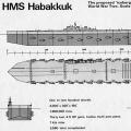 Habakkuk: how the British tried to build an aircraft carrier from ice Why the project was curtailed