Using modern automation equipment. Sectoral analytical system for heat supply control ACS "Heat Disturbance control system
Rice. 6. Two-wire line with two corona wires at different distances between them
16 m; 3 - bn = 8 m; 4 - b,
BIBLIOGRAPHY
1. Efimov B.V. Thunderstorm waves in overhead lines. Apatity: KSC RAS Publishing House, 2000.134 p.
2. Kostenko M.V., Kadomskaya K.P., Levinshgein ML., Efremov I.A. Overvoltage and protection against them in
high voltage overhead and cable power transmission lines. L .: Nauka, 1988.301 p.
A.M. Prokhorenkov
METHODS OF CONSTRUCTION OF AUTOMATED SYSTEM OF DISTRIBUTED CONTROL OF HEAT SUPPLY OF THE CITY
Implementation of resource-saving technologies in modern Russia considerable attention is paid. These issues are especially acute in the regions of the Far North. Fuel oil is used as fuel for urban boiler houses, which is delivered by rail from the central regions of Russia, which significantly increases the cost of generated heat. Duration
the heating season in the Arctic is 2-2.5 months longer than in the central regions of the country, which is associated with the climatic conditions of the Far North. At the same time, heat and power enterprises must generate the required amount of heat in the form of steam, hot water under certain parameters (pressure, temperature) to ensure the life of all urban infrastructures.
Reducing the cost of generating heat supplied to consumers is possible only due to economical combustion of fuel, rational use of electricity for their own needs of enterprises, reducing heat losses to a minimum in the areas of transportation (heating networks of the city) and consumption (buildings, enterprises of the city), as well as reducing the number of service personnel at production sites.
The solution of all these tasks is possible only through the introduction of new technologies, equipment, technical means management to ensure economic efficiency work of heat and power enterprises, as well as improve the quality of management and operation of heat power systems.
Formulation of the problem
One of the important tasks in the field of urban heating is the creation of heat supply systems with the parallel operation of several heat sources. Modern systems district heating in cities has developed as a very complex, spatially distributed systems with closed circulation. The self-regulation property of consumers, as a rule, is absent, the distribution of the coolant is carried out by preliminary installation of specially designed (for one of the modes) constant hydraulic resistances [1]. In this regard, the random nature of the selection of thermal energy by consumers of steam and hot water leads to dynamically complex transient processes in all elements of the thermal power system (TPP).
Operational monitoring of the state of remote objects and control of equipment located at controlled points (CP) are impossible without the development of an automated system for dispatch control and management of central heating points and pumping stations(ASDK and U TSC and NS) cities. Therefore, one of the urgent problems is the control of heat energy flows, taking into account the hydraulic characteristics of both the heating networks themselves and the energy consumers. It requires solving problems associated with the creation of heat supply systems, where in parallel
there are several heat sources (thermal stations - TS)) for a total heating network cities and on the general schedule of heat load. Such systems allow saving fuel during district heating, increasing the load of the main equipment, operating boilers in modes with optimal efficiency values.
Solving problems optimal control technological processes heating boiler room
To solve the problems of optimal control of technological processes of the heating boiler house "Severnaya" of the State Regional Thermal Power Enterprise (GOTEP) "TEKOS" within the framework of the grant of the Program for the Import of Energy Saving and Environmental Equipment and Materials (PIEPOM) of the Russian-American Committee, equipment was supplied (funding from the US government). This equipment and designed for it software allowed to solve a wide range of reconstruction tasks at the base enterprise of GOTEP "TEKOS", and the results obtained - to be replicated at the heat and power enterprises of the region.
The basis for the reconstruction of control systems for boiler units of the TS was the replacement of obsolete automation equipment of the central control panel and local systems automatic regulation to a modern microprocessor-based distributed control system. The implemented distributed control system of boiler units based on the microprocessor system (MPS) TDC 3000-S (Supper) from Honeywell provided a single complex solution for the implementation of all system functions of control of technological processes of the vehicle. The operated MPS possesses valuable qualities: simplicity and clarity of the layout of control and operation functions; flexibility in meeting all the requirements of the process, taking into account the reliability indicators (work in the "hot" standby mode of the second computer and USO), availability and cost-effectiveness; easy access to all system data; simplicity of changing and expanding service functions without feedback on the system;
improved quality of information presentation in a form convenient for decision-making (friendly intelligent operator interface), which helps to reduce errors of operating personnel during the operation and control of vehicle processes; computer creation of the documentation for the automated process control system; increased operational readiness of the facility (the result of self-diagnostics of the control system); promising system with a high degree of innovation. In the TDC 3000 - S system (Fig. 1), it is possible to connect external PLC controllers from other manufacturers (this possibility is realized in the presence of a PLC gateway module). Information from PLC controllers
displayed in the TOC as an array of points available for read-write from user programs. This makes it possible to use distributed I / O stations for data collection, installed in the immediate vicinity of the controlled objects, and transmit data to the TOC via an information cable using one of the standard protocols. This option allows you to integrate new management objects, including automated system dispatching control and management of central heating points and pumping stations (ASDKiU TsTPiNS), in the existing automated process control system of the enterprise without external changes for users.
Local computer network
Universal stations
Computer Applied Historical
gateway module module
Local control network
Backbone gateway
I Reserve (ARMM)
Advanced module an approved process manager (ARMM)
Universal control network
I / O controllers
Cable routes 4-20 mA
Station of input-output SIMATIC ЕТ200М.
I / O controllers
PLC device network (PROFIBUS)
Cable routes 4-20 mA
Flow sensors
Temperature sensors
Pressure Sensors
Analyzers
Regulators
Frequency stations
Gate valves
Flow sensors
Temperature sensors
Pressure Sensors
Analyzers
Regulators
Frequency stations
Gate valves
Rice. 1. Collecting information by distributed PLC stations, transmitting it to TDC3000-S for visualization and processing, followed by issuing control signals
Experimental studies have shown that the processes occurring in a steam boiler in its operating modes are random in nature and refer to non-stationary ones, which is confirmed by the results of mathematical processing and statistical analysis. Taking into account the random nature of the processes occurring in the steam boiler, the estimates of the displacement of the mathematical expectation (MO) M (t) and the variance 5 (?) By the main coordinates of regulation are taken as a measure of the control quality assessment:
Em, (t) 2 MZN (t) - MrN (t) ^ rMih (t) ^ min
where Mzn (t), Mmn (t) are the set and current MO of the main controllable parameters of the steam boiler: the amount of air, the amount of fuel, as well as the steam generating capacity of the boiler.
s 2 (t) = 8 | v (t) - q2N (t) ^ s ^ (t) ^ min, (2)
where 52Tn, 5zn2 (t) are the current and specified dispersion of the main controlled parameters of the steam boiler.
Then the control quality criterion will have the form
Jn = I [abMi (t) + ßsö ;, (t)] ^ min, (3)
where n = 1, ..., j; - ß - weighting factors.
Depending on the boiler operating mode (control or basic), an optimal control strategy must be formed.
For the regulating mode of operation of a steam boiler, the control strategy should be aimed at maintaining the pressure in the steam header constant, regardless of the steam consumption by heat consumers. For this mode of operation, the estimate of the displacement of the steam pressure MO in the main steam header is taken as a measure of the control quality in the form
ep (f) = Pr (1) - Pm () ^ S ^ (4)
where ВД, Рт (0 - set and current average value of steam pressure in the main steam header.
The displacement of the steam pressure in the main steam header in terms of dispersion, taking into account (4), has the form
(0 = -4g (0 ^^ (5)
where (UrzOO, art (0 - set and current pressure dispersion.
Fuzzy logic methods were used to adjust the transmission coefficients of the circuit regulators of the multi-connected boiler control system.
In the process of experimental operation of automated steam boilers, statistical material was accumulated, which made it possible to obtain comparative (with the operation of non-automated boiler units) characteristics of the technical and economic efficiency of the introduction of new methods and controls and to continue reconstruction work on other boilers. So, for the period of six months of operation of non-automated steam boilers No. 9 and 10, as well as automated steam boilers No. 13 and 14, the results were obtained, which are presented in Table 1.
Determination of the parameters of the optimal load of the thermal station
To determine the optimal load of the vehicle, it is necessary to know the energy characteristics of their steam generators and the boiler house as a whole, which represent the relationship between the amount of supplied fuel and the amount of heat received.
The algorithm for finding these characteristics includes the following steps:
Table 1
Boiler performance indicators
Name of indicator Value of indicators of milk yield of boilers
№9-10 № 13-14
Heat generation, Gcal Fuel consumption, t Specific rate of fuel consumption for the production of 1 Gcal of thermal energy, kg of fuel equivalent ^ cal 170 207 20 430 120.03 217 626 24 816 114.03
1. Determination of the thermal performance of boilers for various load modes of their operation.
2. Determination of heat loss A () taking into account the efficiency of boilers and their payload.
3. Determination of the load characteristics of boilers in the range of their variation from the minimum permissible to the maximum.
4. Based on the change in the total heat loss in steam boilers, the determination of their energy characteristics, reflecting the hourly consumption of the equivalent fuel, according to the formula 5 = 0.0342 (0, + AC?).
5. Obtaining the energy characteristics of boiler houses (TS) using the energy characteristics of boilers.
6. Formation, taking into account the energy characteristics of the vehicle, of control decisions on the sequence and order of their loading during the heating period, as well as in the summer season.
Another important issue of organizing the parallel operation of sources (TS) is the determination of factors that have a significant impact on the load of boiler houses, and the tasks of the heat supply management system to provide consumers with the necessary amount of heat energy at the lowest possible cost for its generation and transmission.
The solution of the first problem is carried out by linking the supply schedules with the schedules of heat use by means of a system of heat exchangers, the solution of the second is by establishing the correspondence of the heat load of consumers to its generation, i.e., by planning the load change and reducing losses during the transfer of heat energy. Ensuring the coordination of schedules for the supply and use of heat should be carried out through the use of local automation at intermediate stages from sources of thermal energy to its consumers.
To solve the second problem, it is proposed to implement the functions of assessing the planned load of consumers, taking into account the economically feasible capabilities of energy sources (TS). This approach is possible using situational management methods based on the implementation of fuzzy logic algorithms. The main factor that has a significant impact on
the heat load of boiler houses is that part of it that is used for heating buildings and for hot water supply. The average heat flux (in watts) used to heat buildings is determined by the formula
where / from is the average outside temperature for certain period; d (- average temperature of the internal air of the heated room (the temperature that must be maintained at a given level); / 0 - design temperature of the outside air for heating design;<70 - укрупненный показатель максимального теплового потока на отопление жилых и общественных зданий в Ваттах на 1 м площади здания при температуре /0; А - общая площадь здания; Кх - коэффициент, учитывающий тепловой поток на отопление общественных зданий (при отсутствии конкретных данных его можно считать равным 0,25).
From formula (6) it can be seen that the heat load on heating buildings is determined mainly by the temperature of the outside air.
The average heat flux (in watts) for hot water supply of buildings is determined by the expression
1.2w (a + ^) (55 - ^) p
Yt „. " _ with"
where t is the number of consumers; a - the rate of water consumption for hot water supply at a temperature of +55 ° C per person per day in liters; B - the rate of water consumption for hot water supply, consumed in public buildings, at a temperature of +55 ° C (taken equal to 25 liters per day per person); c - heat capacity of water; / x - temperature of cold (tap) water during the heating period (taken equal to +5 ° С).
Analysis of expression (7) showed that, when calculating, the average heat load on hot water supply turns out to be constant. The real extraction of thermal energy (in the form of hot water from the tap), in contrast to the calculated value, has a random character, which is associated with an increase in the analysis of hot water in the morning and evening, and a decrease in the extraction during the day and night. In fig. 2, 3 are graphs of changes
Oil 012 013 014 015 016 017 018 019 1 111 112 113 114 115 116 117 118 119 2 211 212 213 214 215 216 217 218 219 3 311 312 313 314 315 316 317
days of the month
Rice. 2. The graph of the change in water temperature in the central heating station N9 5 (7 - direct boiler water,
2 - direct quarterly, 3 - hot water supply, 4 - reverse quarterly, 5 - return boiler water) and outside air temperature (6) for the period from 1 to 4 February 2009
pressure and temperature of hot water for central heating station No. 5, which were obtained from the archive of SDKi at the central heating station and the NS of Murmansk.
With the onset of warm days, when the ambient temperature does not drop below +8 ° C for five days, the heating load of consumers is turned off and the heating network works for the needs of hot water supply. The average heat flow to the hot water supply in the non-heating period is calculated by the formula
where is the temperature of cold (tap) water during the non-heating period (taken equal to +15 ° С); р - coefficient taking into account the change in the average water consumption for hot water supply in the non-heating period in relation to the heating period (0.8 - for the housing and communal sector, 1 - for enterprises).
Taking into account formulas (7), (8), the graphs of the heat load of energy consumers are calculated, which are the basis for constructing tasks for the centralized regulation of the heat energy supply of the vehicle.
Automated system of dispatch control and management of central heating points and pumping stations of the city
A specific feature of the city of Murmansk is that it is located on a hilly area. The minimum elevation is 10 m, the maximum is 150 m. In this regard, the heating systems have a heavy piezometric graph. Due to the increased water pressure in the initial sections, the accident rate (pipe ruptures) increases.
For operational monitoring of the state of remote objects and control of equipment located at controlled points (CP),
Rice. 3. Graph of changes in water pressure in the central heating station No. 5 for the period from February 1 to February 4, 2009: 1 - hot water supply, 2 - direct boiler water, 3 - direct quarterly, 4 - reverse quarterly,
5 - cold, 6 - return boiler water
was developed by ASDKiUTSTPiNS of the city of Murmansk. The controlled points, where telemechanics equipment was installed in the course of reconstruction work, are located at a distance of up to 20 km from the head enterprise. Communication with telemechanics equipment at the command post is carried out via a dedicated telephone line. Central boiler rooms (CTP) and pumping stations are separate buildings in which technological equipment is installed. The data from the control panel are sent to the dispatcher's office (to the dispatcher's PCARM) located on the territory of the TS "Severnaya" of the TEKOS enterprise, and to the TS server, after which they become available to users of the local computer network of the enterprise to solve their production problems.
In accordance with the tasks solved with the help of ASDKiUTSTPiNS, the complex has a two-level structure (Fig. 4).
Level 1 (upper, group) - dispatcher's console. The following functions are implemented at this level: centralized control and remote control of technological processes; data display on the control panel display; formation and issuance of
even documentation; formation of tasks in the enterprise's automated process control system for controlling the modes of parallel operation of the city's thermal stations for the general city heating network; access of users of the local network of the enterprise to the technological process database.
Level 2 (local, local) - CP equipment with sensors (alarms, measurements) and terminal actuators located on them. At this level, the functions of collecting and primary processing of information, the issuance of control actions to the executive mechanisms are implemented.
Functions performed by ASDKiUTSTPiNS of the city
Informational functions: control of readings of pressure sensors, temperature, water consumption and control of the state of actuators (on / off, open / closed).
Control functions: control of mains pumps, hot water pumps, other process equipment of the gearbox.
Visualization and registration functions: all informational and alarm parameters are displayed on trends and mnemonic diagrams of the operator station; all informational
Workstation PC of the dispatcher
Adapter ШВ / К8-485
Dedicated phone lines
KP controllers
Rice. 4. Block diagram of the complex
parameters, alarm parameters, control commands are recorded in the database periodically, as well as in cases of state change.
Alarm functions: power outage at the gearbox; triggering of the flooding sensor at the checkpoint and the guard at the checkpoint; alarm from sensors of limit (high / low) pressure in pipelines and from sensors of emergency changes in the state of actuators (on / off, open / closed).
The concept of a support system for making and executing decisions
A modern automated process control system (APCS) is a multilevel man-machine control system. A dispatcher in a multilevel APCS receives information from a computer monitor and acts on objects located at a considerable distance from it using telecommunication systems, controllers, and intelligent executive mechanisms. Thus, the dispatcher becomes the main actor in the management of the technological process of the enterprise. Technological processes in heat power engineering are potentially dangerous. Thus, over thirty years, the number of accounted accidents doubles approximately every ten years. It is known that in steady-state modes of complex energy systems, errors due to inaccuracy of the initial data are 82-84%, due to inaccuracy of the model - 14-15%, due to inaccuracy of the method - 2-3%. Due to the large share of the error in the initial data, an error also arises in the calculation of the objective function, which leads to a significant zone of uncertainty when choosing the optimal operating mode of the system. These problems can be eliminated if we consider automation not just as a way of replacing manual labor directly in production management, but as a means of analysis, forecasting and control. The transition from dispatching to a decision support system means a transition to a new quality - an intelligent information system of the enterprise. Any accident (except natural disasters) is based on human (operator) error. One of the reasons for this is the old, traditional approach to building complex control systems, focused on the use of the latest technology.
technical and technological advances while underestimating the need to use situational management methods, methods of integrating control subsystems, as well as building an effective human-machine interface focused on a person (dispatcher). In this case, the transfer of the functions of the dispatcher for data analysis, forecasting situations and making appropriate decisions to the components of intelligent decision support systems (SPID) is provided. The concept of SPID includes a number of tools, united by a common goal - to facilitate the adoption and implementation of rational and effective management decisions. SPIR is an interactive automated system that acts as an intelligent mediator that supports a natural language user interface with the ZCAAA-system, and uses decision-making rules, corresponding models and bases. Along with this, SPPIR performs the function of automatic support of the dispatcher at the stages of information analysis, recognition and forecasting of situations. In fig. 5 shows the structure of the SPPIR, with the help of which the TS dispatcher controls the heat supply of the microdistrict.
Based on the above, several fuzzy linguistic variables can be distinguished that affect the load of the vehicle, and, consequently, the operation of heating networks. These variables are shown in table. 2.
Depending on the season, time of day, day of the week, as well as the characteristics of the external environment, the situation assessment unit calculates the technical condition and the required performance of thermal energy sources. This approach allows solving the problems of fuel economy during district heating, increasing the load of the main equipment, operating boilers in modes with optimal efficiency values.
The construction of an automated system for the distributed control of the city's heat supply is possible under the following conditions:
introduction of automated control systems for boiler units of heating boiler houses. (Implementation of the APCS at the TS "Severnaya"
Rice. 5. Structure of SPPIR heating boiler house of the microdistrict
table 2
Linguistic Variables Determining the Load of a Heating Boiler House
Designation Name Range of values (universal set) Terms
^ month The month from January to December "Jan", "Feb", "March", "Apr", "May", "June", "July", "Aug", "Sep", "Oct", "Nov" , "Dec"
T-week Day of the week work or day off "work", "day off"
TSug Time of day from 00:00 to 24:00 "night", "morning", "day", "evening"
t 1 n.v Outside air temperature from -32 to + 32 ° С "below", "-32", "-28", "-24", "-20", "-16", "-12", "-8", "^ 1", "0", "4", "8", "12", "16", "20", "24", "28", "32", "above"
1 "в Wind speed from 0 to 20 m / s" 0 "," 5 "," 10 "," 15 "," higher "
ensured a decrease in the specific rate of fuel consumption at boilers No. 13.14 in comparison with boilers No. 9.10 by 5.2%. Electricity savings after installing frequency vector converters on the drives of fans and smoke exhausters of boiler No. 13 was 36% (specific consumption before reconstruction - 3.91 kWh / Gcal, after reconstruction - 2.94 kWh / Gcal, and for the boiler
No. 14 - 47% (specific power consumption before reconstruction - 7.87 kWh / Gcal, after reconstruction - 4.79 kWh / Gcal));
development and implementation of ASDKiUTSTPiNS of the city;
implementation of information support methods for TS and ASDKiUTSTPiNS operators of the city using the SPPIR concept.
BIBLIOGRAPHY
1. Shubin E.P. The main issues of designing heat supply systems for cities. Moscow: Energiya, 1979.360 p.
2. Prokhorenkov A.M. Reconstruction of heating boiler houses on the basis of information and control complexes // Science for production. 2000. No. 2. S. 51-54.
3. Prokhorenkov A.M., Sovlukov A.S. Fuzzy models in control systems of boiler aggregate technological processes // Computer Standarts & Interfaces. 2002. Vol. 24. P. 151-159.
4. Mesarovich M., Mako D., Takahara J. Theory of hierarchical multilevel systems. Moscow: Mir, 1973.456 p.
5. Prokhorenkov A.M. Methods for identification of random process characteristics in information processing systems // IEEE Transactions on instrumentation and measurement. 2002. Vol. 51, No. 3.P. 492-496.
6. Prokhorenkov A.M., Kachala H.M. Processing of random signals in digital industrial control systems // Digital signal processing. 2008. No. 3. S. 32-36.
7. Prokhorenkov A.M., Kachala N.M. Determination of the classification characteristics of random processes // Measurement Techniques. 2008. Vol. 51, No. 4. P. 351-356.
8. Prokhorenkov A.M., Kachala H.M. Influence of the classification characteristics of random processes on the accuracy of processing measurement results // Izmeritelnaya tekhnika. 2008. N ° 8. 3-7.
9. Prokhorenkov A.M., Kachala N.M., Saburov I.V., Sovlukov A.S. Information system for analysis of random processes in nonstationary objects // Proc. of the Third IEEE Int. Workshop on Intelligent Data Acquisition and Advanced Computing Systems: Technology and Applications (IDAACS "2005) Sofia, Bulgaria 2005. P. 18-21.
10. Methods of robust neuro-fuzzy and adaptive control / Ed. N. D. Egupova // M .: Publishing house of MSTU im. N.E. Bauman, 2002 ". 658 p.
P. Prokhorenkov A.M., Kachala N.M. Effectiveness of adaptive algorithms for tuning regulators in control systems subjected to the influence of random disturbances // BicrniK: Scientific and technical. g-l. Special issue. Cherkasy sovereign technol. un-t-Cherkask. 2009.S. 83-85.
12. Prokhorenkov A.M., Saburov I.V., Sovlukov A.S. Data maintenance for processes of decision-making under industrial control // BicrniK: scientific and technical. g-l. Special issue. Cherkasy sovereign technol. un-t. Cherkask. 2009.S. 89-91.
The article is devoted to the use of the Trace Mode SCADA-system for operational-remote control of the city's district heating facilities. The facility on which the described project was implemented is located in the south of the Arkhangelsk region (the city of Velsk). The project provides for the operational supervision and management of the process of preparation and distribution of heat for heating and supplying hot water to the city's vital activities.
CJSC "SpetsTeploStroy", Yaroslavl
Statement of the problem and the necessary functions of the system
The goal of our company was to build a backbone network to supply heat to most of the city using advanced construction methods, where pre-insulated pipes were used to build the network. For this, fifteen kilometers of main heating networks and seven central heating points (CHP) were built. The purpose of the central heating station is using overheated water from the GT-CHPP (according to the schedule 130/70 ° С), prepares the heat carrier for the intra-quarter heating networks (according to the schedule 95/70 ° С) and heats the water up to 60 ° С for the needs of hot water supply (hot water supply), The central heating station operates on an independent, closed circuit.
When setting the problem, many requirements were taken into account that ensure the energy-saving principle of the central heating station. Some of the most important ones are:
Carry out weather-dependent control of the heating system;
Maintain the DHW parameters at a given level (temperature t, pressure P, flow rate G);
Maintain the parameters of the heat carrier for heating at a given level (temperature t, pressure P, flow rate G);
Organize commercial metering of heat energy and heat carrier in accordance with the current regulatory documents (ND);
Provide automatic transfer switch (automatic transfer of reserve) of pumps (network and hot water supply) with equalization of the motor resource;
Correct the main parameters according to the calendar and real time clock;
Perform periodic data transmission to the control room;
Diagnose measuring instruments and operating equipment;
Lack of staff on duty at the central heating station;
Track and promptly inform maintenance personnel about emergency situations.
As a result of these requirements, the functions of the created operational-remote control system were determined. The main and auxiliary means of automation and data transmission were selected. The choice of SCADA-system was made to ensure the operability of the system as a whole.
Necessary and sufficient system functions:
1_Information functions:
Measurement and control of technological parameters;
Signaling and registration of deviations of parameters from the established boundaries;
Formation and delivery of operational data to personnel;
Archiving and viewing the history of parameters.
2_Control functions:
Automatic regulation of important process parameters;
Remote control of peripheral devices (pumps);
Technological protection and blocking.
3_Service functions:
Self-diagnostics of the software and hardware complex in real time;
Data transmission to the control room according to the schedule, upon request and upon the occurrence of an emergency situation;
Testing the performance and correct functioning of computing devices and input / output channels.
What influenced the choice of automation tools
and software?
The choice of the main automation tools was mainly based on three factors - price, reliability and versatility of customization and programming. So, for independent work in the central heating station and for data transmission, free-programmable controllers of the PCD2-PCD3 series from Saia-Burgess were chosen. To create a control room, the domestic SCADA system Trace Mode 6 was chosen. For data transmission, it was decided to use ordinary cellular communication: use a regular voice channel for data transmission and SMS messages to promptly notify personnel about emergency situations.
What is the principle of the system
and features of the implementation of control in Trace Mode?
As in many similar systems, management functions for direct impact on regulatory mechanisms are transferred to the lower level, and already the management of the entire system as a whole - to the upper level. I deliberately omit the description of the work of the lower level (controllers) and the data transfer process and go directly to the description of the upper one.
For ease of use, the control room is equipped with a personal computer (PC) with two monitors. Data from all points are fed to the dispatching controller and transmitted via the RS-232 interface to the OPC server running on a PC. The project is implemented in Trace Mode version 6 and is designed for 2048 channels. This is the first stage in the implementation of the described system.
A feature of the implementation of the task in Trace Mode is an attempt to create a multi-window interface with the ability to monitor the heat supply process in on-line mode, both on the city map and on mnemonic diagrams of heat points. The use of a multi-window interface allows solving the problem of displaying a large amount of information on the dispatcher's display, which must be sufficient and at the same time non-redundant. The principle of a multi-window interface allows access to any process parameters in accordance with the hierarchical structure of windows. And it also simplifies the implementation of the system at the facility, since such an interface is very similar in appearance to the widespread products of the Microsoft family and has similar equipment for menus and toolbars, familiar to any user of a personal computer.
In fig. 1 shows the main screen of the system. It schematically shows the main heating network with an indication of the heat source (CHP) and central heating points (from the first to the seventh). The screen displays information about the occurrence of emergency situations at the facilities, the current outside air temperature, the date and time of the last data transfer from each point. Heating objects are provided with pop-up tips. In the event of an abnormal situation, the object on the diagram starts "blinking", and an event record and a red blinking indicator appear in the alarm report next to the date and time of data transmission. It is possible to view the enlarged thermal parameters for the central heating station and throughout the heating network as a whole. For this, it is necessary to disable the display of the list of alarms and warnings report ("O&P" button).

Rice. one. System main screen. Layout of heat supply facilities in Velsk
The transition to the mnemonic diagram of the substation is possible in two ways - you need to click on the icon on the city map or on the button with the inscription of the substation.
The mnemonic diagram of the substation opens on the second screen. This is done both for the convenience of observing a specific situation at the central heating station, and for monitoring the general state of the system. All monitored and adjustable parameters, including those read from heat meters, are visualized on these screens in real time. All technological equipment and measuring instruments are provided with pop-up tips in accordance with the technical documentation.
The image of equipment and automation equipment on the mnemonic diagram is as close as possible to the real view.
At the next level of the multi-window interface, direct control of the heat transfer process, changing settings, viewing the characteristics of operating equipment, monitoring parameters in real time with a history of changes is carried out.
In fig. 2 shows the screen interface for viewing and managing the main automation equipment (control controller and heat calculator). On the controller control screen, it is possible to change the telephone numbers for sending SMS messages, prohibit or enable the transmission of emergency and information messages, control the frequency and amount of data transmission, set parameters for self-diagnostics of measuring instruments. On the heat meter screen, you can view all the settings, change the available settings and control the mode of communication with the controller.
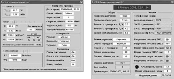
Rice. 2. Control screens for the "Take-off ТСРВ" heat meter and the PCD253 controller
In fig. 3 shows pop-up panels for control equipment (control valve and pump groups). It displays the current status of this equipment, error information and some parameters required for self-diagnostics and verification. So, for pumps, very important parameters are dry running pressure, MTBF and turn-on delay.

Rice. 3. Control panel for pump groups and control valve
In fig. 4 shows screens for monitoring parameters and control loops in a graphical form with the ability to view the history of changes. All monitored parameters of the substation are displayed on the parameter screen. They are grouped according to their physical meaning (temperature, pressure, flow rate, amount of heat, heat output, lighting). The control loops screen displays all parameter control loops and displays the current value of the parameter, set taking into account the dead zone, valve position and the selected control law. All of this data on the screens is paginated, similar to the common design in Windows applications.

Rice. 4. Screens for graphical display of parameters and control loops
All screens can be moved around the space of two monitors, performing multiple tasks at the same time. All the necessary parameters for trouble-free operation of the heat distribution system are available in real time.
How long has the system been developedhow many developers were there?
The basic part of the dispatching and control system in Trace Mode was developed within one month by the author of this article and launched in the city of Velsk. In fig. a photograph is presented from the temporary control room where the system is installed and is undergoing trial operation. At the moment, by the forces of our organization, another heating point and an emergency heat source are being put into operation. It is at these facilities that a special control room is being designed. After its commissioning, all eight heating points will be included in the system.

Rice. five. Temporary workplace of the dispatcher
During the operation of the automated process control system, various comments and suggestions from the dispatching service arise. Thus, the process of updating the system is constantly underway to improve the operational properties and convenience of the dispatcher.
What is the effect of introducing such a management system?
Advantages and disadvantages
In this article, the author does not set the task of assessing the economic effect of the implementation of the management system in numbers. However, the savings are obvious due to the reduction of personnel involved in the maintenance of the system, a significant reduction in the number of accidents. In addition, the environmental impact is evident. It should also be noted that the introduction of such a system allows you to quickly respond and eliminate situations that may lead to unforeseen consequences. The payback period for the entire complex of works (construction of a heating main and heating points, installation and commissioning, automation and dispatching) for the customer will be 5-6 years.
The advantages of a working control system can be cited:
Visual presentation of information on a graphical image of an object;
As for the animation elements, they were specially added to the project to improve the visual effect of viewing the program.
System development prospects
Article 18. Distribution of heat load and management of heat supply systems
1. The distribution of the heat load of heat consumers in the heat supply system between those supplying heat in this heat supply system is carried out by the body authorized in accordance with this Federal Law to approve the heat supply scheme by annually making changes to the heat supply scheme.
2. To distribute the heat load of heat consumers, all heat supply organizations that own sources of heat in this heat supply system are obliged to submit to the body authorized in accordance with this Federal Law to approve the heat supply scheme, an application containing information:
1) on the amount of heat energy that the heat supply organization undertakes to supply to consumers and heat supply organizations in this heat supply system;
2) on the volume of power sources of thermal energy, which the heat supply organization undertakes to maintain;
3) on the current tariffs in the field of heat supply and predicted specific variable costs for the production of heat energy, heat carrier and maintaining capacity.
3. The heat supply scheme must define the conditions under which there is a possibility of heat supply to consumers from various sources of heat energy while maintaining the reliability of heat supply. In the presence of such conditions, the distribution of heat load between heat sources is carried out on a competitive basis in accordance with the criterion of minimum specific variable costs for the production of heat energy by heat sources, determined in the manner prescribed by the basis of pricing in the field of heat supply, approved by the Government of the Russian Federation, based on applications organizations owning sources of heat energy, and standards taken into account when regulating tariffs in the field of heat supply for the corresponding period of regulation.
4. If the heat supply organization does not agree with the distribution of the heat load carried out in the heat supply scheme, it has the right to appeal the decision on such distribution made by the body authorized in accordance with this Federal Law to approve the heat supply scheme to the federal executive body authorized by the Government of the Russian Federation.
5. Heat supply organizations and heating network organizations operating in the same heat supply system are obliged to conclude an agreement between themselves on the management of the heat supply system in accordance with the rules for organizing heat supply approved by the Government of the Russian Federation before the start of the heating season.
6. The subject of the agreement specified in Part 5 of this Article is the procedure for mutual actions to ensure the functioning of the heat supply system in accordance with the requirements of this Federal Law. The prerequisites for this agreement are:
1) determination of the subordination of dispatching services of heat supply organizations and heating network organizations, the procedure for their interaction;
3) the procedure for ensuring access of the parties to the agreement or, by mutual agreement of the parties to the agreement, another organization to the heating networks for setting up heating networks and regulating the operation of the heat supply system;
4) the procedure for interaction between heat supply organizations and heating network organizations in emergencies and emergencies.
7. In the event that heat supply organizations and heating network organizations have not concluded the agreement specified in this article, the procedure for managing the heat supply system is determined by the agreement concluded for the previous heating period, and if such an agreement was not concluded earlier, the specified procedure is established by the body authorized in accordance with this Federal law for the approval of the heat supply scheme.
Siemens is a recognized world leader in the development of energy systems, including heating and water supply systems. This is what one of the Departments does. Siemens - Building Technologies - "Automation and safety of buildings". The company offers a full range of equipment and algorithms for the automation of boiler houses, heating points and pumping stations.
1. The structure of the heat supply system
Siemens offers a comprehensive solution for creating a unified management system for urban heat and water supply systems. The complexity of the approach lies in the fact that customers are offered everything, from performing hydraulic calculations of heat and water supply systems to communication and dispatching systems. The implementation of this approach is ensured by the accumulated experience of the company's specialists, acquired in different countries of the world during the implementation of various projects in the field of heat supply systems in large cities of Central and Eastern Europe. This article discusses the structures of heat supply systems, principles and control algorithms that were implemented in the implementation of these projects.
Heat supply systems are built mainly according to a 3-stage scheme, the parts of which are:
1. Heat sources of different types, interconnected into a single loopback system
2. Central heating points (CHP) connected to the main heating networks with a high coolant temperature (130 ... 150 ° C). In the central heating station, the temperature gradually decreases to a maximum temperature of 110 ° C, based on the needs of the ITP. For small systems, the level of central heating points may be absent.
3. Individual heating points that receive heat energy from the central heating station and provide heat supply to the facility.
A fundamental feature of Siemens solutions is that the entire system is based on the principle of 2-pipe distribution, which is the best technical and economic compromise. This solution makes it possible to reduce heat losses and electricity consumption in comparison with the widespread in Russia 4-pipe or 1-pipe systems with open water intake, investments in the modernization of which are not effective without changing their structure. The maintenance costs of such systems are constantly increasing. Meanwhile, it is the economic effect that is the main criterion for the expediency of the development and technical improvement of the system. Obviously, when constructing new systems, optimal decisions should be made that have been tested in practice. If we are talking about overhaul of the heat supply system of a non-optimal structure, it is economically profitable to switch to a 2-pipe system with individual heating points in each house.
When providing consumers with heat and hot water, the management company incurs fixed costs, the structure of which is as follows:
Heat generation costs for consumption;
losses in heat sources due to imperfect methods of heat generation;
heat losses in heating mains;
R electricity costs.
Each of these components can be reduced with optimal management and the use of modern automation tools at every level.
2. Sources of heat
It is known that for heat supply systems, large sources of combined heat and power generation or those sources in which heat is a by-product, for example, a product of industrial processes, are preferable. It was on the basis of these principles that the idea of district heating arose. Boiler houses operating on different types of fuel, gas turbines, etc. are used as backup heat sources. If gas boilers are the main source of heat, they must operate with automatic optimization of the combustion process. This is the only way to achieve savings and reduce emissions compared to distributed heat generation in each house.
3. Pumping stations
Heat from heat sources is transferred to main heating networks. The heat carrier is pumped by network pumps that run continuously. Therefore, special attention should be paid to the selection and method of operation of the pumps. The operating mode of the pump depends on the modes of heating points. A decrease in the flow rate at the central heating station entails an undesirable increase in the head of the pump (s). Increasing the head negatively affects all system components. At best, only hydraulic noise increases. In any case, electrical energy is lost. Under these conditions, an unconditional economic effect is provided with frequency control of pumps. Various control algorithms are used. In the basic design, the controller maintains a constant differential pressure across the pump by varying the speed. Due to the fact that with a decrease in the flow rate of the coolant, the pressure loss in the lines (quadratic dependence) decreases, it is also possible to reduce the set value (setpoint) of the differential pressure. This pump control is called proportional and can further reduce pump operating costs. More efficient pump control with “remote point” reference correction. In this case, the pressure drop is measured at the end points of the trunk networks. The current differential pressure values compensate for the pressures at the pumping station.
4. Central heating points (CHP)
In modern heat supply systems, CHPs play a very important role. An energy-saving heat supply system should work with the use of individual heating points. However, this does not mean that the central heating stations will be closed: they perform the function of a hydraulic stabilizer and at the same time divide the heat supply system into separate subsystems. In the case of using ITP, central hot water supply systems are excluded from the central heating station. At the same time, only 2 pipes pass through the central heating station, separated by a heat exchanger, which separates the main line system from the ITP system. Thus, the ITP system can operate with other coolant temperatures, as well as with lower dynamic pressures. This guarantees the stable operation of the IHP and at the same time entails a reduction in investment for the IHP. The supply temperature from the CHP is adjusted in accordance with the temperature schedule for the outdoor temperature, taking into account the summer limit, which depends on the demand of the DHW system in the IHP. We are talking about preliminary adjustment of the parameters of the coolant, which makes it possible to reduce heat losses in secondary routes, as well as to increase the service life of the components of thermal automation in the ITP.
5. Individual heating points (ITP)
The operation of the ITP affects the efficiency of the entire heat supply system. ITP is a strategically important part of the heat supply system. The transition from a 4-pipe system to a modern 2-pipe system is fraught with certain difficulties. Firstly, this entails the need for investment, and secondly, without the availability of a certain "know-how", the implementation of ITP can, on the contrary, increase the operating costs of the management company. The principle of operation of the ITP is that the heating point is located directly in the building, which is heated and for which hot water is prepared. At the same time, only 3 pipes are connected to the building: 2 for the heating agent and 1 for cold water supply. Thus, the structure of the pipelines of the system is simplified, and during the planned repair of the routes, there is an immediate saving on the laying of pipes.
5.1. Heating circuit control
The ITP controller controls the heat output of the heating system by changing the temperature of the heat carrier. The heating temperature setpoint is determined from the outdoor temperature and the heating curve (weather-compensated control). The heating curve is determined taking into account the inertia of the building.
5.2. Inertia of the building
The inertia of buildings has a significant impact on the result of weather-dependent heating control. A modern ITP controller must take this influencing factor into account. The inertia of a building is determined by the value of the building's time constant, which ranges from 10 hours for panel houses to 35 hours for brick houses. The ITP controller determines on the basis of the building time constant the so-called "combined" outdoor temperature, which is used as a correction signal in the automatic heating water temperature control system.
5.3. The strength of the wind
Wind significantly affects the room temperature, especially in high-rise buildings located in open areas. The algorithm for correcting the water temperature for heating, taking into account the influence of the wind, provides up to 10% savings in thermal energy.
5.4 Return water temperature limitation
All the controls described above have an indirect effect on reducing the return water temperature. This temperature is the main indicator of the economical operation of the heating system. With different IHP operating modes, the return water temperature can be reduced by means of limiting functions. However, all limiting functions entail deviations from comfort conditions, and their application must be feasible. In independent circuits for connecting the heating circuit with economical operation of the heat exchanger, the temperature difference between the return water of the primary circuit and the heating circuit should not exceed 5 ° C. Efficiency is ensured by the function of dynamic limitation of the return water temperature ( DRT - differential of return temperature ): if the set value of the temperature difference between the return water of the primary circuit and the heating circuit is exceeded, the controller reduces the heating medium flow in the primary circuit. This also reduces the peak load (Fig. 1).
1. The distribution of the heat load of heat consumers in the heat supply system between the heat energy sources supplying heat in this heat supply system is carried out by the body authorized in accordance with this Federal Law to approve the heat supply scheme by annually making changes to the heat supply scheme.
2. To distribute the heat load of heat consumers, all heat supply organizations that own sources of heat in this heat supply system are obliged to submit to the body authorized in accordance with this Federal Law to approve the heat supply scheme, an application containing information:
1) on the amount of heat energy that the heat supply organization undertakes to supply to consumers and heat supply organizations in this heat supply system;
2) on the volume of power sources of thermal energy, which the heat supply organization undertakes to maintain;
3) on the current tariffs in the field of heat supply and predicted specific variable costs for the production of heat energy, heat carrier and maintaining capacity.
3. The heat supply scheme must define the conditions under which there is a possibility of heat supply to consumers from various sources of heat energy while maintaining the reliability of heat supply. In the presence of such conditions, the distribution of heat load between heat sources is carried out on a competitive basis in accordance with the criterion of minimum specific variable costs for the production of heat energy by heat sources, determined in the manner prescribed by the basis of pricing in the field of heat supply, approved by the Government of the Russian Federation, based on applications organizations owning sources of heat energy, and standards taken into account when regulating tariffs in the field of heat supply for the corresponding period of regulation.
4. If the heat supply organization does not agree with the distribution of the heat load carried out in the heat supply scheme, it has the right to appeal the decision on such distribution made by the body authorized in accordance with this Federal Law to approve the heat supply scheme to the federal executive body authorized by the Government of the Russian Federation.
5. Heat supply organizations and heating network organizations operating in the same heat supply system are obliged to conclude an agreement between themselves on the management of the heat supply system in accordance with the rules for organizing heat supply approved by the Government of the Russian Federation before the start of the heating season.
6. The subject of the agreement specified in Part 5 of this Article is the procedure for mutual actions to ensure the functioning of the heat supply system in accordance with the requirements of this Federal Law. The prerequisites for this agreement are:
1) determination of the subordination of dispatching services of heat supply organizations and heating network organizations, the procedure for their interaction;
2) the procedure for organizing the adjustment of heating networks and regulating the operation of the heat supply system;
3) the procedure for ensuring access of the parties to the agreement or, by mutual agreement of the parties to the agreement, another organization to the heating networks for setting up heating networks and regulating the operation of the heat supply system;
4) the procedure for interaction between heat supply organizations and heating network organizations in emergencies and emergencies.
7. In the event that heat supply organizations and heating network organizations have not concluded the agreement specified in this article, the procedure for managing the heat supply system is determined by the agreement concluded for the previous heating period, and if such an agreement was not concluded earlier, the specified procedure is established by the body authorized in accordance with this Federal law for the approval of the heat supply scheme.
 The fastest boat in the world!
 The history of the Off-White brand
 Habakkuk: how the British tried to build an aircraft carrier from ice Why the project was curtailed